Kawasaki Ignition Switch Wiring Diagram – Let’s begin by examining the different types and purposes of the terminals that are found in the ignition switches. These terminals serve for the Ignition button, Coil and Accessory. Once we know the terminals that are utilized and which ones are not, we can identify the different components of the Kawasaki Ignition Switch Wiring Diagram. Then, we will discuss the functions and the Coil. After that, we’ll turn our attention to the Accessory terminals.
The ignition switch’s terminals
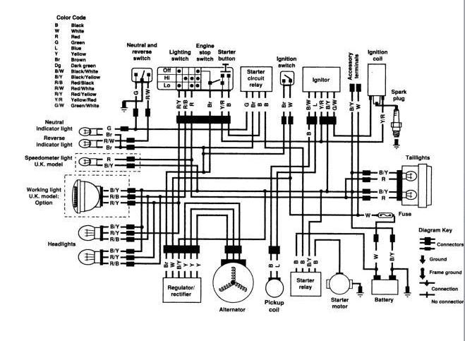
The ignition switch is comprised of three separate switches that feed the battery’s current to different destinations. The choke is powered by the first switch. The second switch controls the ON/OFF function of the ignition switch. Each manufacturer has their individual color-coding system that we’ll go over in a separate article. OMC uses this system. Connectors can be attached to the ignition switch to connect an electronic tachometer.
While the majority of ignition switch terminals don’t carry an original number, they may have a different number. First, check the continuity of all the wires to ensure they are correctly plugged into the ignition switches. This can be done with a multimeter that is inexpensive. Once you’ve verified the integrity of the wires you can then connect the connector. If you are using an ignition switch supplied by the manufacturer the wiring loom will be different from the one used in your vehicle.
Understanding how the ACC outputs are connected to the other outputs inside your car is vital. The ACC, IGN and START terminals are the default connections to the ignition switch. They are also the primary connections to the radio and stereo. The ignition switch regulates the engine in your car. Older cars are identified with the initials “ACC”, “ST”, (for individual magneto cables) on their ignition switch terminals.
Terminals for coil
The language used to decide the type and model of an ignition coil is the first thing. You’ll see a number of connections and terminals in an ignition wiring schematic, including two primary, and two secondary. Each coil has an operating voltage. The first step in determining which kind you’re dealing with is to test the voltage of S1 or the primary terminal. To determine if the coil is a Type A, C or B coil it is recommended to also test S1’s resistance.
The chassis’ negative must be connected to the side of low-tension. This is what’s called the ground in the diagram of the ignition wiring. The high-tension component supplies the spark plugs with positive. The body of the coil has to be connected to the chassis to suppress the effect, but it is not electrically required. A wiring diagram can show the connection between the positive and negative coils. In some instances it is possible to find the ignition coil is damaged and is identified by scanning at an auto parts store.
The black-and-white-striped wire from the harness goes to the negative terminal. Positive terminal receives a second white wire, which has a black trace. The black wire goes to the contact breaker. To check the connections between the two wires, use a paperclip and lift them off the housing. Also, make sure that the connections aren’t bent.
Accessory terminals
The ignition wiring diagrams illustrate the various wires used to power the car’s various parts. There are usually four color-coded terminals that correspond to each component. To identify accessories, red is the starter solenoid’s color, yellow is for battery, and blue for accessory. The “IGN” terminal can be utilized to turn on the car, control the wipers, and other features. The diagram shows how to connect the ACC and ST terminals to the rest of the components.
The terminal called BAT is the place where the battery is. Without the battery the electrical system will not begin. A dead battery could make the switch not turn on. You can refer to your wiring diagram if you’re unsure where your car’s batteries are. The accessory terminals of your vehicle are connected to the battery and ignition button. The BAT Terminal is connected to the Battery.
Certain ignition switches provide an additional “accessory position” that lets users modify their outputs independent of the ignition. Sometimes, customers wish to use an auxiliary output that is separate from the ignition. To use the auxiliary output, connect the connector with the same colors as ignition, and connect it to the ACC terminal on the switch. This option is useful however, it does have one significant distinction. Most ignition switches will have an ACC position when the vehicle is in ACC however, they will be at the START position when the vehicle is IGN.
Gallery of Kawasaki Ignition Switch Wiring Diagram
Gallery of Kawasaki Ignition Switch Wiring Diagram


