Kohler Ignition Coil Wiring Diagram – We will first look at the various kinds and functions of terminals that are found in the ignition switches. These are terminals for Coil, Ignition Switch, and Accessory. Once we have identified what these terminals do then we can identify the different parts in the ignition wiring. We’ll also discuss the functions as well as the Coil. The next step is to focus on the accessory terminals.
Ignition switch terminals

The ignition switch has three switches. They supply the battery’s voltage to many different locations. The first switch provides the choke with power, while the second switch controls the state of the switch. Each manufacturer has their individual color-coding system that we will discuss in another article. OMC uses this method. This connector allows the connection of a speedometer to the ignition switch.
Even though the majority of ignition switch terminals do not have the original design however, the numbers may not be in line with the diagram. You should first check the continuity of the wires to determine if they’re connected to the ignition switch in the correct way. This can be done with a multimeter that is inexpensive. When you’re satisfied with the integrity of your wires, you will be able install the new connector. The wiring loom used for an ignition switch that is factory-supplied will be different than the one in your vehicle.
Before connecting the ACC outputs to your car’s auxiliary outputs It is essential to be familiar with the fundamentals of these connections. The ACC and IGN terminals are the default connections on your ignition switch. the START and IGN terminals are the main connections for the stereo and radio. The ignition switch controls the car’s engine. The terminals of the ignition switch on older cars are labeled with the alphabets “ACC” and “ST” (for individual magneto wires).
Terminals for coil
The language used to decide the type and model of the ignition coil is the most important thing. A basic diagram of the wiring will provide you with a range of terminals and connections. It is essential to identify the kind of coil you have by testing the voltage at the primary terminal S1. To determine if the coil is an A, C or B coil you should also test S1’s resistance.
The low-tension coil side must be connected to the chassis’ less. This is what is known as the ground for the ignition wiring. The high-tension side supplies the spark plugs with positive. To reduce the noise, the coil’s body metal is required to be connected to the chassis. It is not required to use electricity. The ignition wiring diagram will also demonstrate the connections between the positive and negative coil terminals. In some cases, a scan at the local auto parts store will be able to diagnose defective ignition coils.
The black-and-white-striped wire from the harness goes to the negative terminal. The negative terminal is served by the black trace joined to the white wire. The contact breaker is linked to the black wire. You can take the black wire from the plug housing using a paper clip if you are unsure about the connections. Make sure you check that the terminals haven’t been bent.
Accessory terminals
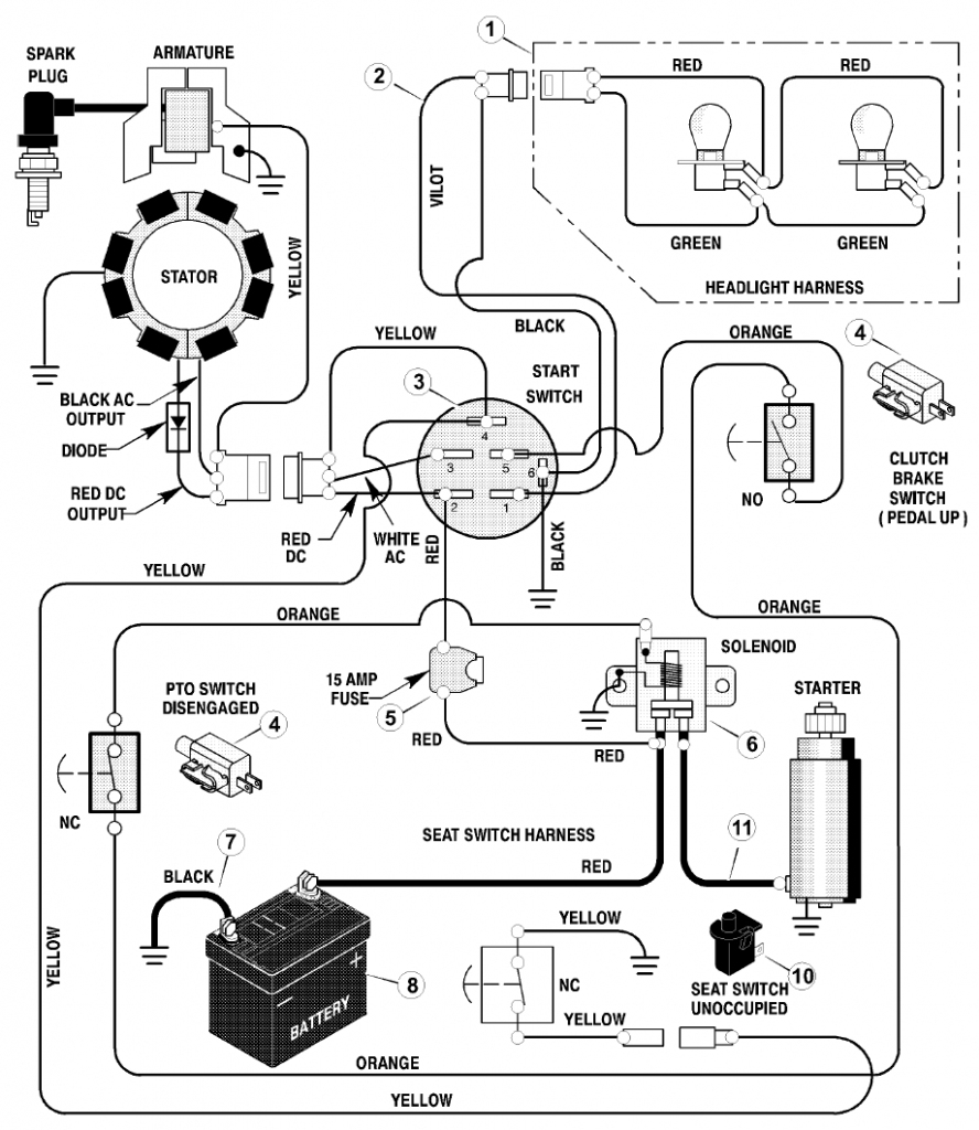
Diagrams of ignition wiring show the wiring used to power the vehicle’s electrical supply. Typically, there are four different colored terminals for each part. Accessories are red and the battery yellow, the starter solenoid is green. The “IGN terminal” is used to run the wipers, and other operating functions. This diagram shows how to connect ACC and ST terminals with the other components.
The terminal BAT is the connector for the battery. Without the battery the electrical system will not start. Also, the switch won’t start without the battery. The wiring diagram will tell the location of your car’s battery. The accessory terminals in your car are connected with the battery and the ignition button. The BAT terminal is connected to the battery.
Certain ignition switches have an additional position. It allows users to connect their outputs to another location without having to turn on the ignition. In some cases, users may want to use the auxiliary input separately from the ignition. Make use of the secondary output by connecting it to an ACC terminal on your switch with the same colors. While this is an excellent option, there’s an important difference. Most ignition switches will be in an ACC position when the vehicle is in ACC however, they’ll be in the START position when the car is in IGN.
Gallery of Kohler Ignition Coil Wiring Diagram
Gallery of Kohler Ignition Coil Wiring Diagram


