Lawn Tractor Ignition Switch Wiring Diagram – Let’s first look at the different terminals on the ignition switch. These include the terminals for the Ignition switch, Coil, and Accessory. Once we have established the purpose of these terminals are for then we can discover the various components of the Lawn Tractor Ignition Switch Wiring Diagram. We will also discuss the functions for the Ignition switch as well as the Coil. The next step is to focus to the accessory terminals.
Terminals for ignition switches
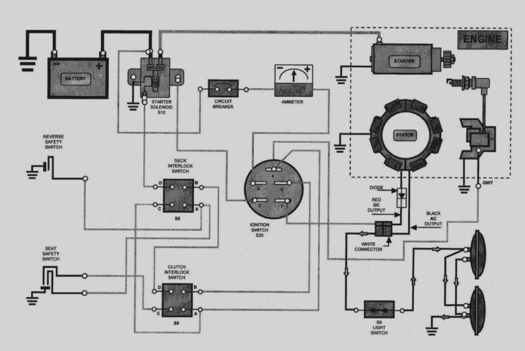
There are three separate switches on an ignition switch that feed the battery’s voltage to various destinations. The first switch supplies power to the choke when pushed, and the second is the position of the ignition switch’s ON/OFF. Each manufacturer has their unique color-coding system, which we’ll go over in a separate article. OMC uses this approach. The ignition switch also includes an adapter for the addition of a tachometer.
While the majority of the ignition switch terminals aren’t original, the numbering for each may not match the diagram. Check the continuity of all the wires to ensure that they are properly connected to the ignition switches. A multimeter that is inexpensive can help you do this. When you’re happy with the quality of the connection then you can connect the new connector. If your vehicle is equipped with an installed ignition switch, the wiring diagram will differ.
The first step is to understand the distinctions between the ACC and auxiliary outputs. The ACC/IGN connections function as the default connections for the ignition switch. The START/IGN terminals connect to the radio or stereo. The ignition switch’s function is to turn the car’s engines on and off. Older vehicles are identified with the alphabets “ACC”, “ST”, (for individual magneto cables) on their ignition switch’s terminals.
Terminals for Coil
The terminology used to determine the kind and model of an ignition coil is the primary thing. The basic ignition wiring diagram illustrates a variety of connections and terminals. There are two primary and one secondary. Each coil comes with its own operating voltage. To determine what kind of coil you’ve got first, you need to test the voltage at S1, the primary terminal. To determine if it is an A, C, or B coil you must also check the resistance of S1.
The negative of the chassis must be connected to the low-tension side. This is exactly what you can find in the diagram of wiring. The high-tension component supplies positively directly to the spark plugs. For suppression purposes the coil’s metal body is required to be connected to the chassis. It is not required to use electricity. The ignition wiring diagram will also outline the connection of the positive coil’s terminals. Sometimes, a damaged ignition coil is identified through a scan performed at an auto parts shop.
The black-and-white-striped wire from the harness goes to the negative terminal. Positive terminal receives a second white wire, which is black in its trace. The black wire is connected to the contact breaker. To check the connections, you can employ a paperclip, or a pencil to lift them out from the plug housing. Be sure the terminals don’t bend.
Accessory terminals
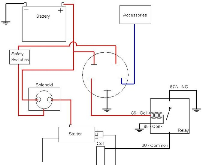
Diagrams of the ignition wiring illustrate the wiring used to provide power to various components of the vehicle. There are usually four different color-coded terminals to each component. The red color is used for accessories and yellow is for the battery, and green is for the solenoid for starters. The “IGN” terminal lets you start your car, operate the wipers or other functions. The diagram shows the connection of the ACC- and ST terminals.
The terminal BAT connects the battery to the charger. The electrical system can’t be started without the battery. Also, the switch won’t be able to turn on without the battery. It is possible to refer to your wiring diagram if you are uncertain about where the car’s batteries are. The ignition switch and the battery are connected by the accessory terminals. The BAT terminal is connected to the battery.
Some ignition switches offer the option of an “accessory position” that lets users adjust their outputs independently of the ignition. Some customers want the output of the auxiliary to be operated independently of the ignition. To allow the auxiliary output to be used, plug in the connector in the same shade as that of the ignition. Connect it to the ACC end of the switch. This option is useful however it does have one significant distinction. A lot of ignition switches can be programmed to have an ACC position when the vehicle has moved into the ACC position. They’ll also be in START mode after the vehicle has been entered the IGN position.
Gallery of Lawn Tractor Ignition Switch Wiring Diagram
Gallery of Lawn Tractor Ignition Switch Wiring Diagram


