Lumenition Magnetronic Ignition Wiring Diagram – We will first look at the various types of terminals for the ignition switch. These terminals comprise the Ignition switch, the Coil and the Accessory. After we’ve established what these kinds of terminals are for We will then determine the various parts of the Lumenition Magnetronic Ignition Wiring Diagram. We’ll also go over the roles of the Ignition switch and the Coil. We’ll then turn our attention on the accessory terminals.
The terminals are for ignition switches.
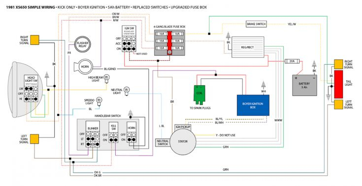
An ignition switch is made up of three different switches. They are responsible for feeding the battery’s energy to various places. The first switch provides power to the choke when pushed, and the second is the position of the ignition switch’s ON/OFF. Different manufacturers have different color codes for different conductors. This is discussed in a separate article. OMC utilizes the same system. Connectors can be connected to the ignition switch to add the digital tachometer.
Although the majority of ignition switch terminals can be duplicated, the numbers may not be consistent with the diagram. To make sure that your wires are properly connected to the ignition switch you must verify their continuity. This can be done using an inexpensive multimeter. After you’re happy with the integrity of your wires, you’ll be able to connect the new connector. If your car is equipped with an original factory-supplied ignition switch (or wiring loom) The wiring loom may differ from that of your vehicle.
Before connecting the ACC outputs to the auxiliary outputs of your car It is essential to know the fundamentals of these connections. The ACC and IGN terminals are the default connection on your ignition switch, and the START and IGN terminals are the principal connections to the stereo and radio. The ignition switch is the one that turns the engine of your car on and off. Older cars are identified by the alphabets “ACC”, “ST”, (for individual magneto cables) at the ignition switch’s terminals.
Coil terminals
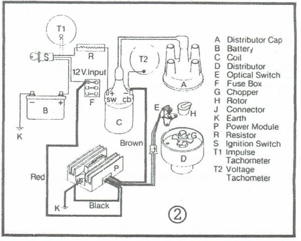
The first step in determining the kind of ignition coil is to understand the terminology employed. You will see several connections and terminals within a basic ignition wiring schematic that include two primary as well as two secondary. Each coil is equipped with a distinct operating voltage. To determine which type of coil you’ve got first, you need to determine the voltage at S1, which is the primary terminal. S1 must be tested for resistance in order to determine if the coil is type A, B and/or C.
The chassis’ negative must be connected to connect the coil’s low-tension end. This is what’s called the ground in the diagram of the ignition wiring. The high-tension part connects the spark plugs to a positive. The body of the coil has to connect to the chassis for suppression purposes, but it is not electrically necessary. The wiring diagram will also show the connection between the positive and negative coil terminals. Sometimes, a defective ignition coil can be identified by a scan done at an auto repair shop.
The black-and-white-striped wire from the harness goes to the negative terminal. The positive terminal is connected to the white wire with a black trace. The contact breaker is attached to the black wire. It is possible to check the connections with a paperclip to take the wires out from the housing. Also, see that the terminals are not bent.
Accessory terminals
The wiring diagrams of the ignition illustrate the different wires that power the various components of the car. Each component is equipped with four distinct color-coded connections. Red refers to accessories, yellow the battery, and green is the starter solenoid. The “IGN terminal” is used to power the wipers and other operating functions. The diagram below shows how to connect both the ACC terminal and ST terminals to various components.
The terminal BAT is where the battery is. The electrical system won’t start if the battery isn’t connected. A dead battery could make the switch not turn on. The wiring diagram will tell you where to find the battery of your car. The accessory terminals in your vehicle connect to the battery and the ignition switch. The BAT terminal is connected to the battery.
Some ignition switches come with an additional “accessory position” that lets users modify their outputs independent of the ignition. Users may wish to use the auxiliary output separately from the ignition. You can use the auxiliary output by connecting the connector to the ACC terminal on the switch that has the same color. This feature of convenience is fantastic, but there is one distinction. A lot of ignition switches can be programmed to have an ACC position once the car has been moved into the ACC position. They will also be in START mode after the vehicle has been entered the IGN position.
Gallery of Lumenition Magnetronic Ignition Wiring Diagram
Gallery of Lumenition Magnetronic Ignition Wiring Diagram


