Mallory Ignition Wiring Diagram Unilite – We will first look at the various types of terminals on the ignition switch. The terminals are the Ignition switch as well as the Coil as well as the Accessory. When we have a clear understanding of the purpose of each kind of terminal, we can then determine the components of the ignition wiring. We’ll also discuss the functions as well as the Coil. Then we’ll move on to the Accessory Terminals.
Terminals for the ignition switch
There are three separate switches on an ignition switch, which provide the battery’s voltage to various places. The first one supplies the choke with power when it is pushed. The second is the switch that controls the ignition’s ON/OFF positions. Different manufacturers use different color-coding systems that correspond to the conductors. OMC utilizes this system. The connector allows for the attachment of a speedometer the ignition switch.
Even though most ignition switch terminals don’t have an original number, they may have a different one. First, check the continuity of all the wires to ensure that they are properly connected to the ignition switches. This can be accomplished using a cheap multimeter. When you’re satisfied that the wires are running in good harmony then you can connect the new connector. The wiring loom of an ignition system switch that is supplied by the manufacturer is different.
It is important to understand the ways in which the ACC outputs and the auxiliary outputs work in order to join them. The ACC and IGN connectors are the standard connections for the ignition switch. The START, IGN, and ACC terminals are primary connections for the radio or stereo, the START/IGN connections are the most important ones. The ignition switch is accountable to turn the engine of your car on and off. Older vehicles have ignition switch terminals marked “ACC” or “ST” (for individual magnetowires).
Terminals for coil
The terminology used to determine the type and model of the ignition coil is the primary thing. You will see several connections and terminals within a basic ignition wiring schematic that include two primary and two secondary. Each coil is operating at a certain voltage. The first step to determine which kind you have is to check the voltage on S1, or the primary terminal. S1 must also be subjected to resistance tests to determine if it’s a Type A or B coil.
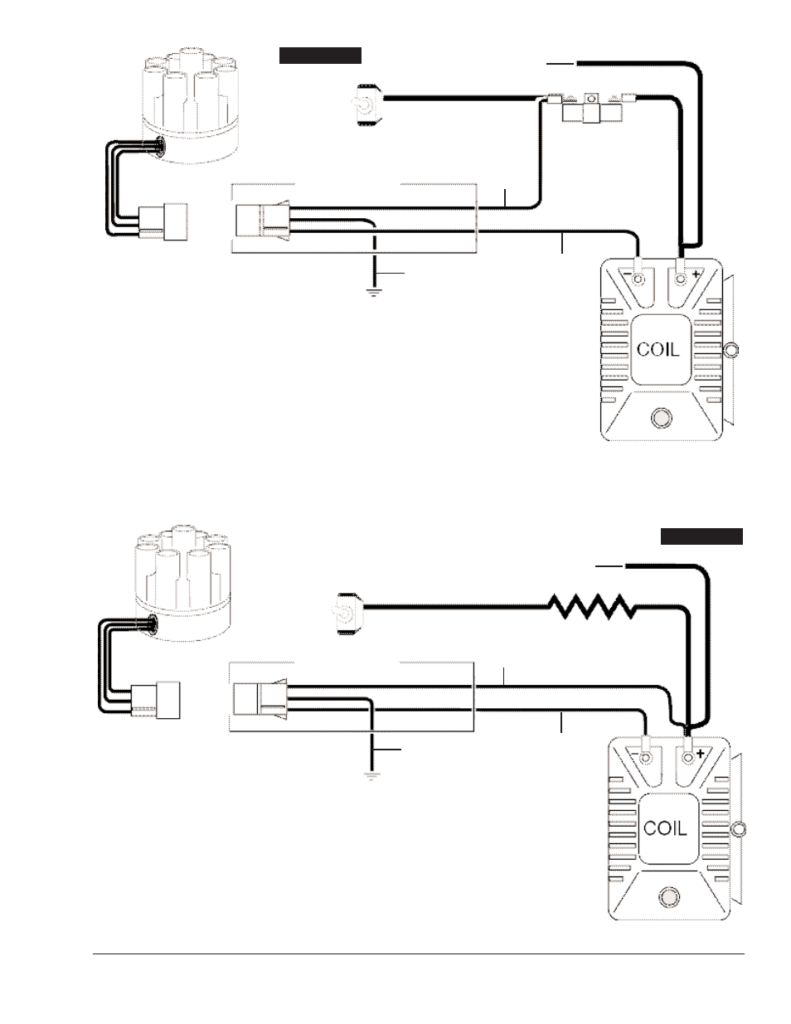
The negative end of the chassis must be connected to connect the coil’s low-tension side. It is also the ground in the diagram of ignition wiring. The high-tension part connects the spark plugs to a positive. The metal body of the coil needs to connect to the chassis to suppress the effect, but it is not electrically required. There are also connections between the positive and the negative coil’s terminals on an diagram of the ignition wiring. Sometimes, a check at an auto parts store could detect a defective ignition wire.
The black-and-white-striped wire from the harness goes to the negative terminal. Positive terminal receives a second white wire, which is black in its trace. The contact breaker is linked to the black wire. If you’re not certain about the connection between the two, try using a paper clip to remove them from the plug housing. It is also important to make sure the terminals don’t bend.
Accessory terminals
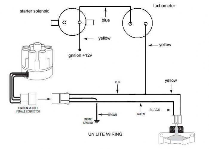
The diagrams for ignition wiring illustrate the wiring used to power the vehicle’s electrical supply. There are generally four color-coded terminals to each component. The accessories are red and the battery yellow and the starter solenoid green. The “IGN terminal is used to start the vehicle, controlling the wipers and various other functions. The diagram illustrates how to connect ACC or ST terminals as well as the rest.
The terminal BAT is the connector for the battery. The battery is vital for the electrical system to begin. A dead battery can cause the switch to stop turning on. If you’re not sure where your car’s battery is located, you can look at the wiring diagram of your car to determine the best way to find it. The accessory terminals in your car are connected to the ignition switch and the battery. The BAT terminal is connected to the battery.
Some ignition switches come with an additional “accessory position” that lets users alter their outputs without the ignition. Some customers prefer to use an auxiliary output that is independent of the ignition. To use the auxiliary output, wire the connector using the same colors as the ignition connecting it to the ACC terminal on the switch. This is an excellent feature, but there is an important difference. The majority of ignition switches have an ACC position if the car is in the ACC however, they will be in the START position if the vehicle is in IGN.
Gallery of Mallory Ignition Wiring Diagram Unilite
Gallery of Mallory Ignition Wiring Diagram Unilite


