Marine Ignition Switch Wiring Diagram – First, we will look at the different types of terminals that are found in the ignition switch. These are the terminals that connect the Ignition, Coil, or Accessory. Once we know what these kinds of terminals are used for, we will proceed to identify the different parts of the Marine Ignition Switch Wiring Diagram. We’ll also discuss the functions and the Coil. Then, we’ll turn our attention to Accessory terminals.
Ignition switch terminals
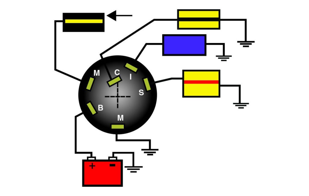
Three switches can be found on the ignition switch. Each of these three switches is able to feed the battery’s voltage to a variety of places. The first switch provides the choke with power when pushed, and the second is the switch that controls the ignition’s ON/OFF positions. Different manufacturers have different color-coding schemes to identify different conductors. We’ll discuss this in a separate article. OMC employs this system. The ignition switch also includes a connector for adding an tachometer.
While most ignition switch terminals are duplicated, the numbers might not match the diagram. First, check the continuity of each wire to ensure that they are properly connected to the ignition switches. This can be done using a cheap multimeter. When you are happy with the continuity of the wires it is time to connect the new connector. The wiring loom used for the ignition switch supplied by the manufacturer will differ from the one in your vehicle.
Before you can connect the ACC outputs to the auxiliary outputs of your car It is essential to be familiar with the fundamentals of these connections. The ACC and IGN terminals are the default connections on the ignition switch. the START and IGN terminals are the primary connections to the stereo and radio. The ignition switch turns the car’s engine on and OFF. In older vehicles the terminals of the ignition switch are marked with the initials “ACC” as well as “ST” (for distinct magnet wires).
Terminals for coil
Understanding the terminology is the first step towards knowing what type of ignition coil you have. The fundamental diagram of ignition wiring shows a number different connections and terminals. There are two primary and one secondary. The operating voltage of each coil differs. Therefore, it is crucial to test the voltage at S1 (primary terminal). You should also test S1 for resistance in order to identify if it’s a Type A B, C, or coil.
The low-tension end of the coil should be connected to the chassis’ negative. This is the wiring diagram you will find in the wiring diagram. The high-tension side supplies positively directly to the spark plugs. To reduce the noise, the coil’s metal body is required to be connected to the chassis. It is not necessary to electrically connect. It is also possible to see the connections between the positive and the negative coil’s terminals on the diagram of the ignition wiring. It is possible to find an issue with the ignition coil which can be identified by scanning it at an auto parts retailer.
The black-and-white-striped wire from the harness goes to the negative terminal. The positive terminal receives the white wire with a trace in black. The black wire goes to the contact breaker. To check the wires’ connections, employ a paperclip to remove them out of the housing. It is also important to make sure that the terminals don’t bend.
Accessory terminals
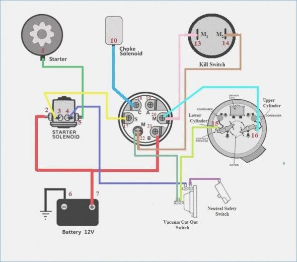
The ignition wiring diagrams illustrate the various wires utilized to power the vehicle’s various parts. There are generally four colored terminals for each component. The red color is used for accessories while yellow is the battery, and green is the starter solenoid. The “IGN” terminal is used to turn on the car , and also to operate the wipers as well as other operational features. The below diagram illustrates how to connect the ACC terminal as well as the ST terminals to various components.
The terminal BAT connects the battery to the charger. The battery is essential for the electrical system to start. A dead battery could make the switch stop turning on. It is possible to refer to your wiring diagram if unsure where your car’s batteries are. The accessory terminals in your car are connected to the battery and the ignition button. The BAT connector is connected to the battery.
Some ignition switches come with an accessory position. This lets users connect their outputs to a different location without the ignition. Sometimes, customers want to use an auxiliary output that is not connected to the ignition. Use the additional output by connecting the connector to an ACC terminal on your switch with the same colors. This is a great convenience feature however, there’s one differentiator. The majority of ignition switches are set up to show an ACC status when the car’s in the ACC or START position.
Gallery of Marine Ignition Switch Wiring Diagram
Gallery of Marine Ignition Switch Wiring Diagram


