Marine Ignition Wiring Diagram – We will first look at the various types of terminals that are used on the ignition switch. These terminals are used for the Ignition button, Coil and Accessory. When we have a clear understanding of the purpose of each kind of terminal, we are able to determine the components of the ignition wiring. We’ll also go over the functions for the Ignition switch, as well as the Coil. Following that, we will discuss the Accessory Terminals.
Terminals for ignition switch
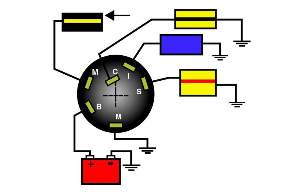
The ignition switch consists of three different switches. They are responsible for supplying the battery’s power to various places. The first switch powers the choke. The third switch regulates the ON/OFF function of the ignition switch. Different manufacturers have different colour-coding systems that correspond to the conductors. OMC utilizes this system. A tachometer adapter is installed on the ignition switch to allow the addition of the tonometer.
Even though most ignition switch terminals don’t have an original number, they might have a different number. Check the integrity of the wires to see if they are connected to the ignition switch in the correct way. This can be done with a simple multimeter. After you have verified that the wires are in good condition, you can then connect the connector. The wiring loom in the ignition system switch supplied by the manufacturer is distinct.
Before connecting the ACC outputs to the auxiliary outputs of your car it is crucial to understand the basics of these connections. The ACC, IGN and START terminals are your default connections to the ignition switch. They are also the main connections to the radio and stereo. The ignition switch switches the car’s engine ON and OFF. Older cars are equipped with ignition switch terminals marked “ACC” or “ST” (for individual magnetowires).
Terminals for coil
Understanding the terminology is the first step towards knowing what type of ignition coil you have. The basic ignition wiring diagram shows a number different connections and terminals. There are two primary and secondary connections. The operating voltage of each coil differs. It is essential to first check the voltage at the S1 (primary terminal). S1 should also be checked for resistance in order to identify if the coil is an A, Type B or A coil.
The low-tension side of the coil needs to be connected to the chassis”negative. It is also the ground on the diagram of ignition wiring. The high-tension supply delivers positive directly to spark plugs. It is essential for the purpose of suppression that the metallic body of the coil is connected to its chassis however it isn’t essential. The diagram of the ignition wiring will also show the connection of the positive coil’s terminals. Sometimes, a malfunctioning ignition coil can be detected through a scan performed at an auto repair shop.
The black-and-white-striped wire from the harness goes to the negative terminal. The positive terminal is connected to the white wire, which has an black trace. The contact breaker is attached to the black wire. To test the wires’ connections, use a paperclip and lift them from the housing. Also, make sure to ensure that the terminals haven’t been bent.
Accessory terminals
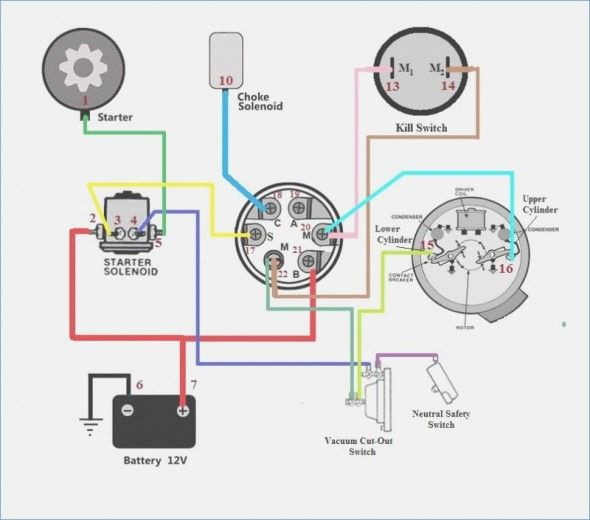
Diagrams of ignition wiring show the various wires that are used to power different components. There are generally four colored terminus lines for each component. For accessories, red stands for starter solenoid, blue for battery, and blue is for accessory. The “IGN terminal is used for starting the car, operating the wipers and various other functions. The below diagram shows how to connect both the ACC terminal and ST terminals to the other components.
The terminal known as BAT is where the battery is connected. The electrical system won’t start in the event that the battery isn’t connected. In addition, the switch doesn’t turn on. If you don’t know the location of your car’s battery situated, examine your wiring diagram to see where it is. The ignition switch is connected to the car’s battery. The BAT terminal is connected with the battery.
Some ignition switches are equipped with an additional position. This lets users connect their outputs to another location without having to turn on the ignition. In some cases, users may want to use the auxiliary input independently of the ignition. Use the secondary output by connecting the connector to the ACC terminal on your switch with the same colors. This feature is convenient however, it does have one key difference. A majority of ignition switches feature the ACC position when your vehicle is in the ACC mode and a START mode when the switch is in IGN.
Gallery of Marine Ignition Wiring Diagram
Gallery of Marine Ignition Wiring Diagram


