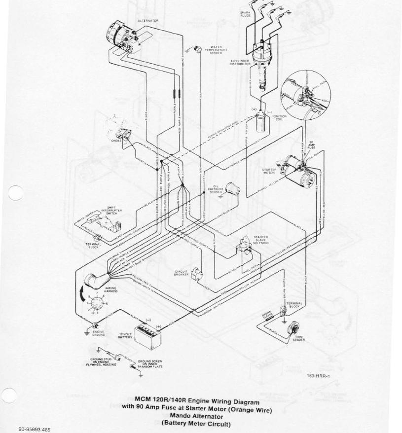
Mercruiser 3.0 Ignition Wiring Diagram – Let’s start by looking at the different types terminals found on the ignition switch. These are terminals for the Ignition, Coil, or Accessory. Once we’ve established the purpose of the terminals we can recognize the various parts of the ignition wiring. We’ll also discuss the functions of both the Ignition Switch and Coil. After that, we will turn our attention towards the accessories terminals.
Terminals for ignition switches
The ignition switch consists of three different switches. They are responsible for supplying the battery’s power to several destinations. The first switch powers the choke. The second switch controls the ON/OFF function of the ignition switch. Different manufacturers have distinct colour-coding systems that correspond to the conductors. OMC utilizes this system. The connector permits the attachment of a speedometer to the ignition switch.
Although the majority of ignition switch terminals may not be original, the numbers for each one may not be in line with the diagram. To ensure that your wires are properly connected to the ignition switch it is recommended to check their continuity. This can be accomplished using an inexpensive multimeter. After you’re happy with the continuity of your wires, you will be able to install the new connector. The wiring loom used in an ignition system switch that is supplied by the manufacturer is different.
Knowing how the ACC outputs are connected to the other outputs inside your vehicle is crucial. The ACC and IGN connectors are the default connections of your ignition switch. The START, IGN, and ACC terminals are primary connections for the radio or stereo, the START/IGN terminals are the most important ones. The ignition switch turns the engine of your car ON and off. The terminals of older vehicles ignition switches are identified with “ACC” and ST (for specific magneto wires).
Terminals for coil
Understanding the terms is the initial step in finding out what kind of ignition coil you’ve got. In a basic diagram of the wiring for ignition, you will see several different connections and terminals, which include two primary and two secondary. The coils have a specific operating voltage. The first step to determine which one you have will involve testing the voltage at S1, the main terminal. You should also examine S1 for resistance to determine whether it is a Type A, B, or C coil.
The coil’s low-tension side should be connected at the chassis’s plus. This is what is known as the ground for the wiring for ignition. The high-tension component supplies positively direct to the spark plugs. To reduce the noise the coil’s metal body is required to be connected to the chassis. It is not required for electrical use. It is also possible to see the connections between the positive and negative coil’s terminals on the diagram of the ignition wiring. In some cases it is possible to find a malfunctioned ignition coil can be diagnosed with scans in an auto parts store.
The black-and-white-striped wire from the harness goes to the negative terminal. The terminal that is negative is served by the trace in black that’s attached to the white wire. The black wire is connected to the contact breaker. To verify the wires’ connections, employ a paperclip to lift them from the housing. Also, make sure to verify that the connections haven’t been bent.
Accessory terminals
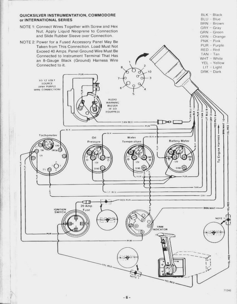
Diagrams of ignition wiring illustrate the wiring used to provide power to various components of the car. There are generally four colors of terminals connected to each part. Red stands for accessories, yellow represents the battery and green for the starter solenoid. The “IGN” terminal is used to start the vehicle, controlling the wipers and various other functions. The diagram shows the connection to the ACCand ST terminals.
The terminal BAT connects the battery to the charger. The electrical system won’t start if the battery isn’t connected. The switch won’t be able to turn off if the battery isn’t present. If you’re not sure of the location of your car’s battery located, you can review your wiring diagram to see where it is. The accessory terminals of your car are connected with the battery as well as the ignition button. The BAT terminal is connected to the battery.
Certain ignition switches come with an “accessory” setting that allows users to control their outputs , without having to use the ignition. In some cases, users may want to utilize the auxiliary input independently of the ignition. The auxiliary output is connected by wiring the connector with the same colors as the ignition, and then attaching it to the ACC terminal of the switch. This feature of convenience is fantastic however, there’s one distinction. Most ignition switches are configured to operate in the ACC position when the vehicle is in the ACC position, whereas they’re in the START position when the car is in the IGN position.
Gallery of Mercruiser 3.0 Ignition Wiring Diagram
Gallery of Mercruiser 3.0 Ignition Wiring Diagram


