Mercury Ignition Switch With Choke Wiring Diagram – In the beginning, we’ll take a look at the various kinds of terminals that are found on the ignition switch. These are the terminals that connect the Ignition, Coil, or Accessory. After we’ve identified the purpose of the terminals we can recognize the various parts of the ignition wiring. In addition, we will discuss the functions of the Ignition switch and Coil. Following that, we’ll shift our attention to the Accessory terminals.
Terminals of ignition switch
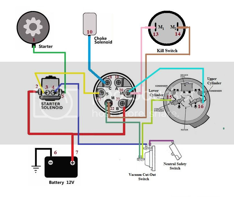
An ignition switch has three different switches that direct the battery’s power to various locations. The first switch provides the choke with power when it is pushed. The second is the position of the ignition switch’s ON/OFF. Different manufacturers use various color codes for the various conductors. This is discussed in another article. OMC uses this method. There is a connector in the ignition switch to allow connecting an to a tachometer.
While most ignition switch terminals can be duplicated, the number may not be in line with the diagram. Before plugging into the ignition switch ensure that you check the continuity. A multimeter that is inexpensive can assist you in this. When you’re satisfied that the wires are running in good harmony then you can connect the new connector. The wiring loom used for the ignition switch supplied by the factory will be different from the one that you have in your car.
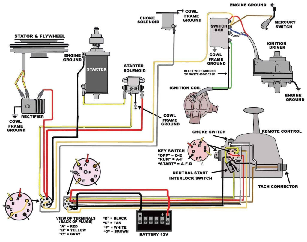
To connect the ACC outputs to the auxiliary outputs of your car, you need to understand the way these two connections function. The ACC and IGN terminals are the default connections on the ignition switch. the START and IGN terminals are the main connections for radio and stereo. The ignition switch is accountable for turning the car’s engine on and off. In older vehicles the terminals of the ignition switch are identified with the letters “ACC” as well as “ST” (for individual magnet wires).
Terminals for coil
Understanding the terms utilized is the first step in determining the kind of ignition coil to choose. A basic ignition wiring layout will reveal a variety of terminals and connections. You need to determine the kind of coil you have by testing the voltage on the primary terminal, S1. S1 must also be inspected for resistance to determine if the coil is an A, Type B or A coil.
The low-tension side of the coil should be connected to the chassis”negative. This is the ground on the ignition wiring diagram. The high-tension part is a positive connection to the sparkplugs. To prevent noise the coil’s body metal must be connected to the chassis. This is not necessary for electrical use. The wiring diagram for the ignition will explain how to connect the terminals of the negative or positive coils. In certain cases it is recommended to conduct a scan at your local auto parts store can help you identify the malfunctioning ignition coils.
The black-and-white-striped wire from the harness goes to the negative terminal. Positive terminal receives the white wire that includes a black trace. The black wire connects to the contactbreaker. To test the connections between the two wires, employ a paperclip to remove them from the housing. Be sure the terminals aren’t bent.
Accessory terminals
Diagrams of ignition wiring illustrate the wires that are used in the vehicle’s power supply. There are typically four color-coded terminals to each component. For accessories, red stands for starter solenoid, blue for battery, and blue for accessories. The “IGN” terminal can be used to start the car, turn on the wipers, as well as other features. The diagram illustrates how you can connect ACC or ST terminals, and other.
The terminal BAT is the connection to the battery. Without the battery, the electrical system does not begin. Furthermore, the switch won’t start. It is possible to look up your wiring diagram to determine where the batteries of your car are situated. Your car’s accessory terminals connect to the ignition switch as well as the battery. The BAT terminal is connected to the battery.
Some ignition switches feature an additional “accessory” position, in which users can control their outputs without the ignition. Sometimes, customers want to use an auxiliary output that is independent of the ignition. For the auxiliary output to be used, wire the connector to the same color as that of the ignition. Then connect it with the ACC end of the switch. This is a great convenience feature however, there’s one difference. Most ignition switches are configured to have an ACC status when the car’s at the ACC or START positions.
Gallery of Mercury Ignition Switch With Choke Wiring Diagram
Gallery of Mercury Ignition Switch With Choke Wiring Diagram


