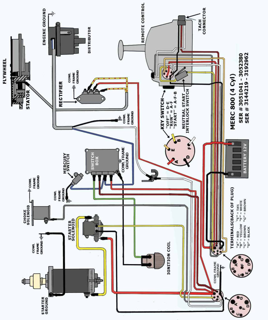
Mercury Marine Ignition Switch Wiring Diagram – Let’s first examine the different types and purposes of the terminals found in the ignition switches. These are terminals for the Ignition, Coil, or Accessory. Once we know the purpose of each type of terminal, it is possible to identify the parts of the ignition wiring. Then, we will discuss the functions and the Coil. Then, we’ll talk about the roles of the Ignition switch and Coil.
The terminals of the ignition switch
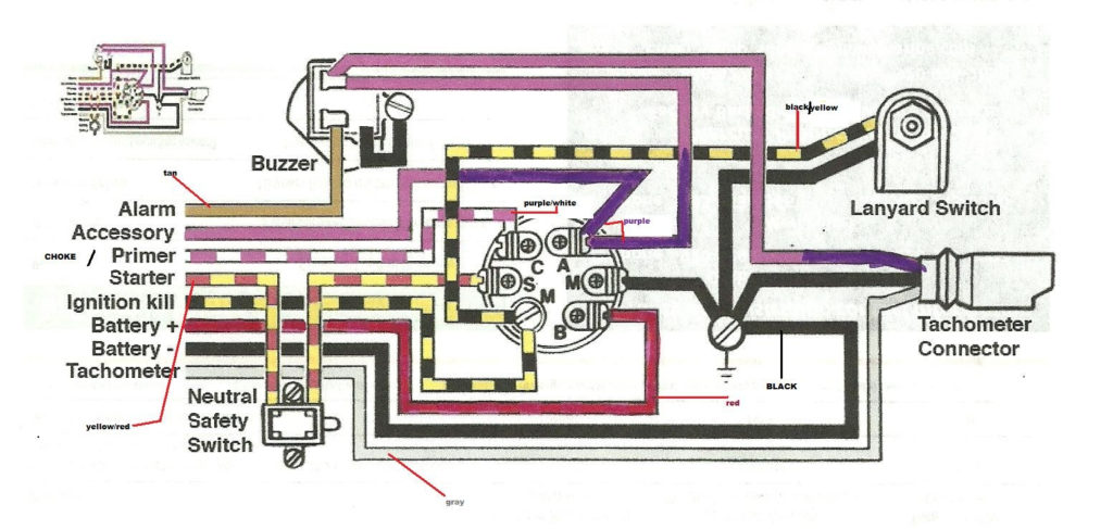
Three switches can be found on an ignition switch. Each of the three switches transmits the battery’s current to various destinations. The ON/OFF position of the ignition switch is controlled by the second switch, which provides the choke with power when it is pushed. Different manufacturers have different colors for various conductors. This is discussed in a separate article. OMC utilizes this system. The adapter is attached to the ignition switch that allows for the addition of an tonometer.
While most ignition switch terminals may not be original, the numbers for each might not be consistent with the diagram. Before plugging into the ignition switch ensure that you check the continuity. You can check this using a simple multimeter. When you’re happy with the continuity, you can place the new connector. The wiring loom for an ignition switch that is factory-supplied will be different than the one in your vehicle.
It is essential to know the ways in which the ACC outputs and the auxiliary outputs work in order to connect them. The ACC and IGN connectors are the default connections of your ignition switch. Although the START, IGN, and ACC terminals are primary connections for the radio or stereo, the START/IGN terminals are the primary ones. The ignition switch acts as the engine’s switch to turn off or on. The terminals of older cars ignition switches are marked with “ACC” as well as ST (for specific magneto wires).
Terminals for coil
The language used to decide the model and type of the ignition coil is the first thing. A simple diagram of the wiring will display a range of connections and terminals, including two primary and two secondaries. The operating voltage of each coil differs. It is important to first test the voltage at S1 (primary terminal). S1 should also be tested for resistance in order to identify if it’s a Type B, B, or A coil.
The coil’s low-tension side must be connected to the chassis’ positive. This is also the ground on an ignition wiring diagram. The high-tension side supplies the spark plugs with positive. It is essential to suppress the coil’s metallic body be connected to its chassis, however it isn’t essential. The wiring diagram for ignition will also outline the connection of the positive coil’s terminals. In some cases, you’ll find that a malfunctioned ignition coil is easily identified with scans in an auto parts store.
The black-and-white-striped wire from the harness goes to the negative terminal. The other white wire is black and connects to the terminal opposite. The black wire is connected to the contact breaker. If you’re unsure of the connections of the twowires, use an old paper clip to take them from the housing of the plug. Be sure the terminals do not bend.
Accessory terminals
Diagrams of ignition wiring show the wiring used in the power supply of the vehicle. There are usually four colors-coded terminus of each part. For accessories, red is for starter solenoid, blue for battery and blue for accessory. The “IGN” terminal is used for starting the car, operating the wipers and other functions. The diagram shows the connections to the ACC- and ST terminals.
The terminal BAT is where the battery is. The electrical system won’t start without the battery. A dead battery can cause the switch to not turn on. If you’re not sure of the location of your car’s battery located, you can examine your wiring diagram to figure out how to locate it. The ignition switch and battery are connected via accessory terminals. The BAT Terminal is connected to the Battery.
Some ignition switches are equipped with an additional position. It allows users to access their outputs from another location without having to turn on the ignition. Some customers might want to use the auxiliary input independently of the ignition. In order for the auxiliary output be used, plug in the connector to the same color as that of the ignition. Then , connect it to the ACC end of the switch. Although this is a great feature, there’s something to be aware of. Most ignition switches will have an ACC position if the car is in the ACC however, they will be in the START position when the vehicle is in IGN.
Gallery of Mercury Marine Ignition Switch Wiring Diagram
Gallery of Mercury Marine Ignition Switch Wiring Diagram


