Mk4 Golf Ignition Switch Wiring Diagram – The first step is to examine the different types of terminals for the ignition switch. They include terminals for the Ignition switch, Coil, and Accessory. Once we’ve determined the function of the terminals we can recognize the various parts of the ignition wiring. In addition, we will discuss the functions of the Ignition switch, and Coil. Then, we’ll turn our attention to the Accessory terminals.
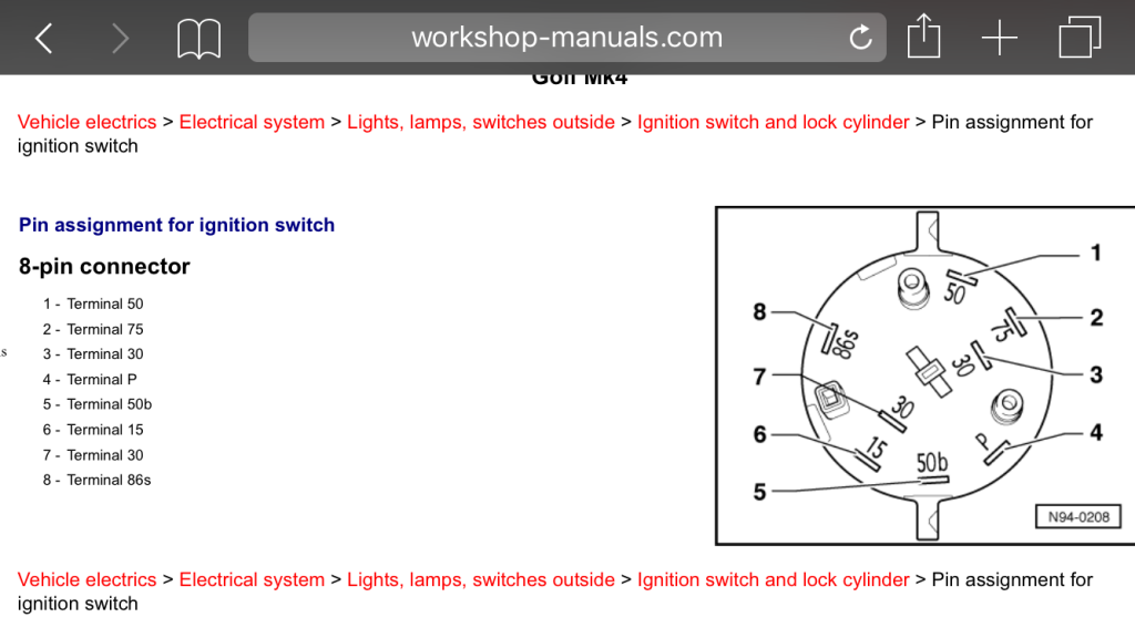
Terminals for ignition switches
An ignition switch is made up of three switches. They are responsible for supplying the battery’s power to various destinations. The ON/OFF position of the ignition switch is controlled by the second switch, which supplies the choke with power when it is pushed. Different manufacturers employ different color codes for various conductors. This is discussed in another article. OMC utilizes this system. Connectors can be connected to the ignition switch in order to add the digital tachometer.
While the majority of ignition switch terminals don’t carry an original number, they might have a different one. Before plugging in the ignition switch, ensure that you check the continuity. You can do this with an inexpensive multimeter. After you’re happy with the integrity of the wires, then you’ll be able to connect the new connector. The wiring loom used for an ignition switch that is supplied by the factory will be different from the one that you have in your car.
It is essential to know the way that ACC outputs and the auxiliary outputs function to connect them. The ACC and IGN connectors are the standard connections of your ignition switch. Although the START, IGN, and ACC terminals are the main connections for the radio or stereo, the START/IGN terminals are the most important ones. The ignition switch turns the engine of your car ON and OFF. The terminals of older vehicles ignition switches are identified with “ACC” as well as ST (for individual magneto wires).
Terminals for coil
Understanding the terminology is the first step to determining which type of ignition coil you’ve got. An understanding of the basic wiring diagram for ignition will show you a number of terminals and connections. Each coil comes with its own operating voltage. To determine which type of coil you’ve got the first step is to check the voltage at S1, which is the primary terminal. S1 should be tested for resistance in order to determine if the coil is Type A, B, or C.
The low-tension side of the coil must be connected to the chassis’ negative. This is also the ground in the ignition wiring diagram. The high-tension component connects the spark plugs to a positive. For suppression purposes the coil’s body metal must be connected to the chassis. It’s not necessary for electrical use. The wiring diagram will illustrate the connection between the positive and negative coil terminals. There could be an issue with the ignition coil that is easily identified by looking it up at an auto parts retailer.
The black-and-white-striped wire from the harness goes to the negative terminal. Positive terminal gets the white wire that is black in its trace. The black wire connects to the contactbreaker. You can examine the connections with a pencil to pull the wires out from the housing. Also, make sure to check that the terminals have not been bent.
Accessory terminals
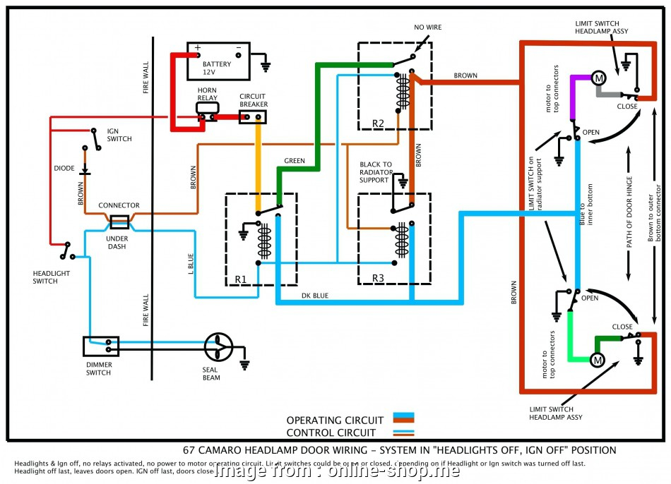
The ignition wiring diagrams illustrate the various wires used to power the car’s various components. There are generally four color-coded terminals to each component. The accessories are red, the battery is yellow and the starter solenoid green. The “IGN terminal” is used to run the wipers, as well as other operating functions. This diagram shows how to connect ACC and ST terminals with the rest of components.
The terminal BAT connects the battery to the charger. The electrical system won’t start without the battery. The switch will not turn off if the battery isn’t there. If you don’t know where your car’s battery is located, you can look at your wiring diagram to figure out the best way to find it. The ignition switch as well as the battery are connected by the accessory terminals. The BAT terminal is connected to the battery.
Some ignition switches come with an additional “accessory” position, in which users can control their outputs with no ignition. Customers may want to utilize the auxiliary output independently of the ignition. The auxiliary output can be connected by wiring the connector with the same color as your ignition, and then attaching it to the ACC terminal of the switch. This is an excellent feature, however there’s an important distinction. The majority of ignition switches are set to be in an ACC position when the vehicle is in the ACC position, whereas they’re set to the START position when the vehicle is in the IGN position.
Gallery of Mk4 Golf Ignition Switch Wiring Diagram
Gallery of Mk4 Golf Ignition Switch Wiring Diagram


