Mopar Ignition Wiring Diagram – Let’s begin by examining the different kinds and functions of terminals in the ignition switches. These are terminals for the Ignition, Coil, or Accessory. After we’ve identified the purpose of the terminals we can recognize the various parts of the ignition wiring. We’ll also discuss the functions as well as the Coil. Next, we’ll discuss the functions of the Ignition switch as well as Coil.
Terminals for ignition switches
An ignition switch has three switches. They transmit the battery’s voltage to different places. The ON/OFF state of the switch that controls the ignition is managed by the second switch, which supplies the choke with power when it’s pulled. Different manufacturers use different color-coding systems that correspond to the conductors. OMC follows this procedure. This connector allows the attachment of a speedometer the ignition switch.
Even though the majority of ignition switch terminals don’t have the original design The numbering might not match the diagram. It is important to first verify the continuity of the wires to ensure that they are plugged into the correct ignition switch. This can be accomplished with a simple multimeter. Once you’re satisfied about the integrity of the wires, then you’ll be able to install the new connector. If you’re using an ignition switch supplied by the manufacturer the wiring loom may be different from that in your car.
In order to connect the ACC outputs to the auxiliary outputs of your car, you’ll need to understand the way these two connections function. The ACC and IGN terminals are the default connection on the ignition switch. the START and IGN terminals are the principal connections to the stereo and radio. The ignition switch acts as the engine’s on/off button. On older vehicles the ignition switch’s terminals are marked with the letters “ACC”, and “ST” (for the individual magnet wires).
Terminals for coil
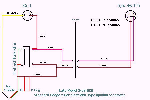
The terminology used to determine the type and model of the ignition coil is the most important thing. The diagram of the basic ignition wiring depicts various connections and terminals. There are two primary and secondary connections. Each coil has a specific operating voltage. To determine the type of coil you own the first step is to test the voltage at S1, which is the primary terminal. To determine if it is a Type A, C or B coil you must also check the resistance of S1.
The coil’s low-tension component must be connected to the chassis positive. This is the ground on the ignition wiring diagram. The high-tension part provides the spark plugs with positive. To prevent noise the coil’s body metal must be connected with the chassis. This is not necessary to use electricity. There are also connections between the positive and negative coil’s terminals on an ignition wiring diagram. In some cases, you’ll find that a malfunctioned ignition coil is easily identified with scans in an auto parts store.
The black-and-white-striped wire from the harness goes to the negative terminal. Positive terminal receives a white wire that has a black trace. The black wire connects to the contactbreaker. You can examine the connections with a pencil to pull the wires out of the housing. Be sure to ensure that the terminals have not been bent.
Accessory terminals
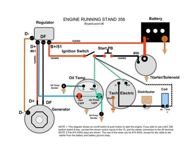
Diagrams of the ignition wiring illustrate the wires used to provide power to various components of the vehicle. In general there are four colored terminals for each part. The red color represents accessories, yellow is for the battery and green for the solenoid for starters. The “IGN terminal” is used to provide power to the wipers and other operating features. This diagram shows how you can connect ACC and ST terminals with the rest of the components.
The terminal known as BAT is the place where the battery is. The electrical system will not start without the battery. Additionally the switch isn’t turned on. If you’re not sure of the location of your car’s battery situated, review the wiring diagram of your car to determine the best way to find it. The accessory terminals in your car are connected with the battery as well as the ignition button. The BAT terminal connects to the battery.
Some ignition switches are equipped with an accessory position. This lets users connect their outputs to another location without the ignition. Users may wish to utilize the auxiliary output independently of the ignition. The auxiliary output is utilized to connect the connector in the same color as your ignition and connecting it to the ACC terminal of the switch. This convenience feature is great, but there is one differentiator. The majority of ignition switches have an ACC position when the vehicle is in the ACC however they’ll be in the START position if the vehicle is in IGN.
Gallery of Mopar Ignition Wiring Diagram
Gallery of Mopar Ignition Wiring Diagram


