Motoplat Ignition Wiring Diagram – We will first examine the different types of terminals for the ignition switch. These are the terminals for the Ignition, Coil, or Accessory. After we’ve identified the purpose of these terminals, we will be able to recognize the various parts of the ignition wiring. We will also discuss the roles of the Ignition switch as well as the Coil. The next step is to focus on the accessory terminals.
Ignition switch terminals
An ignition switch contains three different switches that direct the battery’s current to various locations. The first is used to power the choke through pushing it. Then, the second is for the ON/OFF position. Different manufacturers use different colors-coding systems to match the conductors. OMC employs this system. The ignition switch comes with an option to connect an Tachometer.
Although the majority of ignition switch terminals aren’t original, the numbering for each may not match the diagram. To ensure that your wires are plugged in to the ignition switch, you should check their continuity. This can be checked with a simple multimeter. When you’re satisfied that all wires are in good continuity and you are able to connect the new connector. If you are using a factory-supplied ignition switch the wiring loom will be different from that you have in your car.
It is essential to know the way that ACC outputs and the auxiliary outputs function to join them. The ACC, IGN and START terminals are your default connection to the ignition switch. They also serve as the main connections to the radio and stereo. The ignition switch switches the car’s engine on and OFF. The terminals on older cars ignition switches are marked by “ACC” and ST (for specific magneto wires).
Terminals for coil
Understanding the terminology that is used is the initial step towards determining the kind of ignition coil to choose. An understanding of the basic wiring diagram for ignition will provide you with a range of connections and terminals. Each coil comes with its own operating voltage. To determine what kind of coil you own the first step is to check the voltage at the S1 primary terminal. S1 should also be tested for resistance to determine if the coil is a Type B, B or an A coil.
The coil’s low-tension component is to be connected to the chassis positive. This is also the ground in the wiring diagram for ignition. The high-tension part connects the spark plugs to a positive. For suppression purposes the body of the coil must be connected to the chassis. However, it is not required to connect electrically. The ignition wiring diagram will also show you how to connect the positive and negative coil terminals. In certain instances scanning the local auto parts store will be able to diagnose defective ignition coils.
The black-and-white-striped wire from the harness goes to the negative terminal. The other white wire has a black color and connects to the negative terminal. The black wire connects to the contact breaker. You can check the connections with a paperclip to remove the wires from the housing. It is also important to see that the terminals aren’t bent.
Accessory Terminals
Ignition wiring diagrams show the different wires that are utilized to power the vehicle’s various components. Each part has four distinct colored connections. Red is used to indicate accessories, yellow is the battery, and green for the starter solenoid. The “IGN” terminal is used to turn on the car and operate the wipers as well as other operational features. The diagram below shows how to connect the ACC terminal and ST terminals to the other components.
The terminal BAT is the connection to the battery. Without the battery the electrical system can not get started. The switch also won’t be able to turn on without the battery. It is possible to view the wiring diagram of your car to see where the batteries of your car are placed. The ignition switch and battery are connected by the accessory terminals. The BAT terminal is connected to the battery.
Certain ignition switches have an additional “accessory” position, in which users can manage their outputs with no ignition. Some customers prefer to utilize an additional output that is not connected to the ignition. The auxiliary output could be utilized to connect the connector in the same color as your ignition, and then connecting it to the ACC terminal of the switch. This is a convenient feature, but it has one key distinction. Many ignition switches can be programmed to have an ACC location when the car is in the ACC position. They will also be in the START mode once the vehicle is moved into the IGN position.
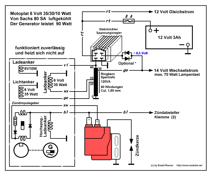
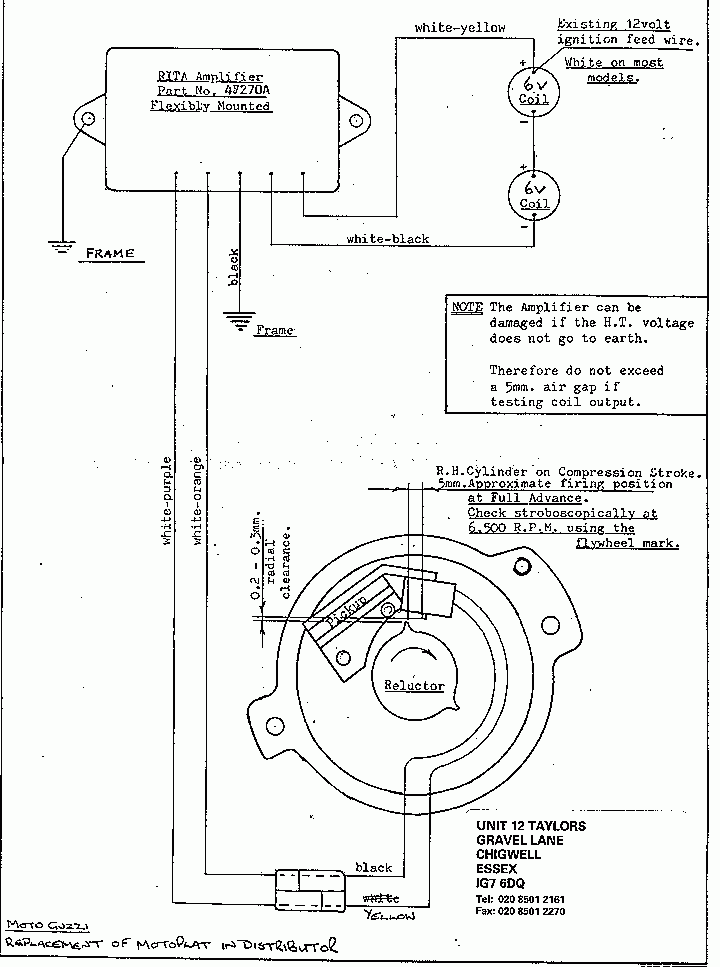
Gallery of Motoplat Ignition Wiring Diagram
Gallery of Motoplat Ignition Wiring Diagram


