Motorcycle Ignition System Wiring Diagram – In the beginning, we’ll examine the various types of terminals that are found in the ignition switch. They include terminals for the Ignition switch, Coil, and Accessory. Once we’ve established the purpose of the terminals we can recognize the various parts of the ignition wiring. In addition, we will discuss the roles of both the Ignition Switch and Coil. Following that, we’ll shift our attention to Accessory terminals.
Ignition switch terminals
There are three switches on an ignition switch that feed the battery’s voltage to various locations. The first one supplies power to the choke when it is pushed. The third is the switch that controls the ignition’s ON/OFF positions. Different manufacturers utilize their own color-coding method for the different conductors, which is documented in another article. OMC utilizes this approach. This connector allows the attachment of a speedometer the ignition switch.
While most ignition switch terminals are duplicated, the number may not match the diagram. It is important to first verify the electrical continuity to see if they are connected to the ignition switch correctly. This can be done using a cheap multimeter. After you’re happy with the continuity of your wires, you will be able to connect the new connector. If you are using an ignition switch that is supplied by the manufacturer the wiring loom may be distinct from the one that is used in your vehicle.
Knowing how the ACC outputs are connected to the auxiliary outputs in your car is vital. The ACC, IGN and START terminals are your default connection to the ignition switch. They also serve as the primary connections to the radio and stereo. The ignition switch is responsible for turning the engine of your car on and off. The terminals of the ignition switch on older cars are identified with the letters “ACC” as well as “ST” (for individual magneto wires).
Terminals for coil
The terms used to define the model and type of the ignition coil is the first thing. A simple diagram of the wiring will show a variety of connections and terminals, including two primary and two secondary. Each coil has a specific operating voltage. To determine what kind of coil you have, the first step is to check the voltage at S1, the primary terminal. S1 should be examined for resistance to determine if the coil belongs to Type A, B, and/or C.
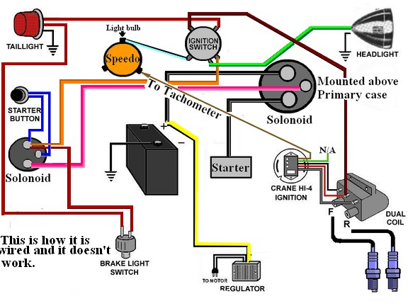
The coil’s low-tension end must be connected with the chassis’ positive. This is the base of the wiring for ignition. The high-tension side delivers positive direct to the spark plugs. For suppression purposes the coil’s body metal must be connected to the chassis. This is not necessary to use electricity. The wiring diagram will illustrate the connection between the positive and negative coils. Sometimes, a damaged ignition coil can be detected through a scan performed at an auto parts shop.
The black-and-white-striped wire from the harness goes to the negative terminal. The positive terminal receives the white wire and a trace in black. The black wire connects to the contact breaker. You can take the black wire from the housing of the plug with a paper clip if you are unsure about the connections. You should also check to see that the terminals are not bent.
Accessory terminals
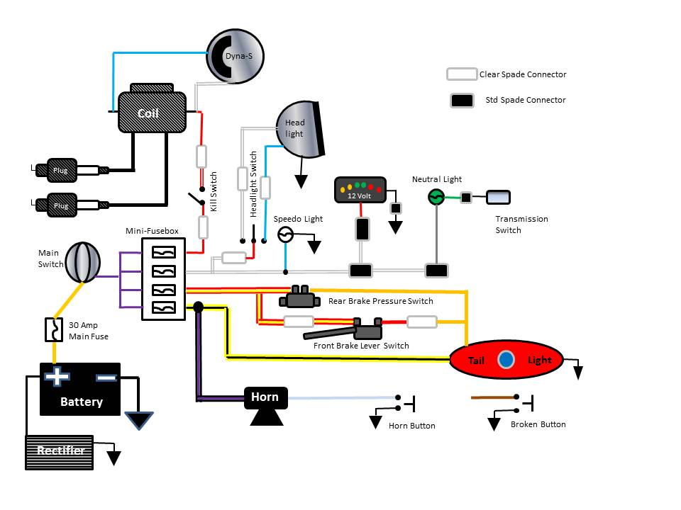
The ignition wiring diagrams illustrate the various wires that are used to power various components of the car. Each component is equipped with four distinct connections that are color coded. Red is for accessories while yellow is the battery, while green is for the solenoid for starters. The “IGN terminal” is used to provide power to the wipers along with other operational functions. The below diagram illustrates how to connect the ACC terminal as well as the ST terminals to other components.
The terminal BAT connects the battery to the charger. The electrical system won’t start in the event that the battery isn’t connected. In addition, the switch will not begin to turn on. The wiring diagram will tell you where to find the battery of your car. The accessory terminals of your vehicle are connected to the battery and ignition button. The BAT Terminal is connected to the Battery.
Some ignition switches feature the “accessory” setting that allows users to control their outputs , without needing to turn on the ignition. Some customers may prefer to use the auxiliary output in addition to the ignition. To make use of the auxiliary output, wire the connector in the same colors as ignition, connecting it to the ACC terminal on the switch. This convenience feature is great, but there is one differentiator. Most ignition switches are configured to have an ACC status when the car’s at either the ACC or START position.
Gallery of Motorcycle Ignition System Wiring Diagram
Gallery of Motorcycle Ignition System Wiring Diagram


