Omc Ignition Switch Wiring Diagram – Let’s begin by examining the different kinds and functions of terminals in the ignition switches. These terminals include the Ignition switch, the Coil along with the Accessory. After we’ve identified the terminals used, we can begin to identify the different components of the Omc Ignition Switch Wiring Diagram. Then, we will discuss the functions and the Coil. Then, we’ll talk about the roles of the Ignition switch as well as Coil.
Terminals of ignition switch
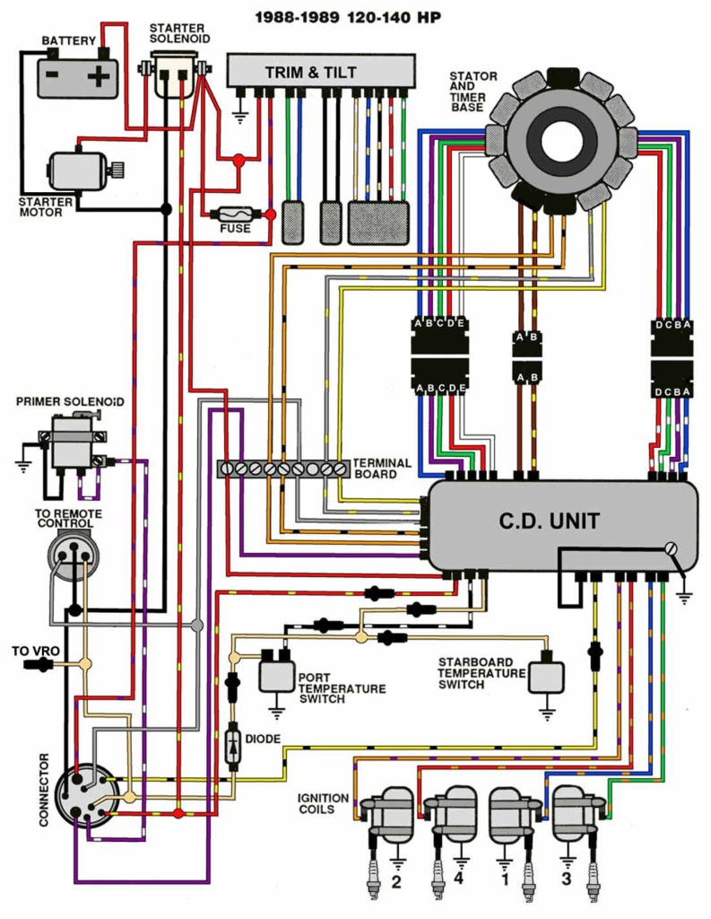
Three switches are found on the ignition switch. Each of the three switches is able to feed the battery’s voltage to a variety of locations. The ON/OFF position of the ignition switch is controlled by the second switch, which provides power to the choke whenever it is pushed. Different manufacturers have distinct color-coding systems that correspond to the conductors. OMC utilizes this method. A connector is also included inside the ignition switch for connecting the to a tachometer.
While the majority of ignition switch terminals don’t have an initial number, they could have a different number. Before plugging into the ignition switch, ensure that you check the continuity. A multimeter that is inexpensive can help you do this. Once you are satisfied that the wires are running in good harmony and you are able to connect the new connector. If your car has an original factory-supplied ignition switch (or an electrical loom), the wiring loom may differ from that of your car.
To connect the ACC outputs to the auxiliary outputs on your car, you need first know how these two connections work. The ACC and IGN terminals are the default connections on your ignition switch. the START and IGN terminals are the main connections for the radio and stereo. The ignition switch is the engine’s switch to turn off or on. Older vehicles have ignition switch’s terminals that are labeled “ACC” or “ST” (for individual magnetowires).
Terminals for coil
Understanding the terms is the first step towards knowing what type of ignition coil you own. In a simple ignition wiring diagram there are several different terminals and connections, including two primary and two secondary. The operating voltage of each coil is different. It is important to first test the voltage at the S1 (primary terminal). Also, you should examine S1 for resistance in order to determine if it’s an A B, C, or coil.
The lower-tension side of the coil needs to be connected to the chassis the negative. This is what is known as the ground for the ignition wiring. The high-tension side is a positive connection to the sparkplugs. To prevent noise, the coil’s metal body must be connected to the chassis. It is not necessary to connect the coil electrically. The wiring diagram for the ignition will show you how to connect the two terminals of the positive or negative coils. Sometimes, a malfunctioning ignition coil can be identified by a scan done at an auto parts shop.
The black-and-white-striped wire from the harness goes to the negative terminal. The positive terminal also receives the second white wire, which includes a black trace. The black wire is connected to the contactbreaker. To verify the connections, employ a paperclip, or a pencil to pull them out of the housing for the plug. Make sure you ensure that the terminals have not been bent.
Accessory terminals
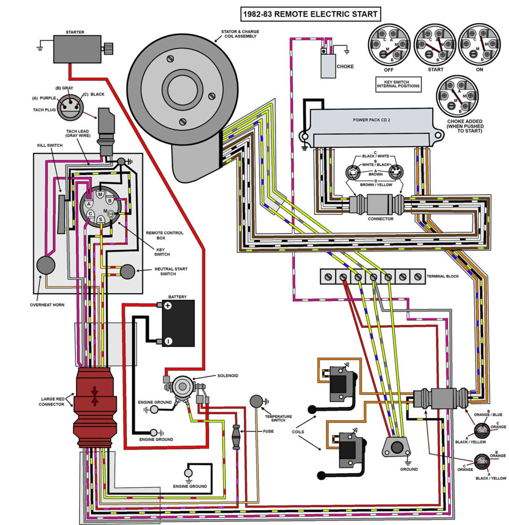
The diagrams for ignition wiring depict the wires that are used in the power supply of the vehicle. There are generally four colored terminals that correspond to the respective component. Red refers to accessories, yellow to the battery and green is the starter solenoid. The “IGN terminal is used to start the car, controlling the wipers, and for other functions. The diagram shows how you can connect the ACC and ST terminals to the rest of the components.
The battery is connected to the terminal called BAT. The battery is vital for the electrical system to begin. In addition, the switch will not start. If you’re not sure the exact location where the battery in your car is situated, you can examine your wiring diagram to figure out where it is. The accessory terminals on your car connect to the battery and the ignition switch. The BAT terminal is connected to the battery.
Certain ignition switches come with an additional position in which users can adjust their outputs as well as control them without the need to use the ignition. Some customers prefer to utilize an additional output that is independent of the ignition. Make use of the auxiliary output by connecting the connector to an ACC terminal on the switch using the same colors. This feature is convenient however it does have one significant difference. Some ignition switches are programmed to have an ACC location when the car has moved into the ACC position. They will also be in the START position after the vehicle has been moved into the IGN position.
Gallery of Omc Ignition Switch Wiring Diagram
Gallery of Omc Ignition Switch Wiring Diagram


