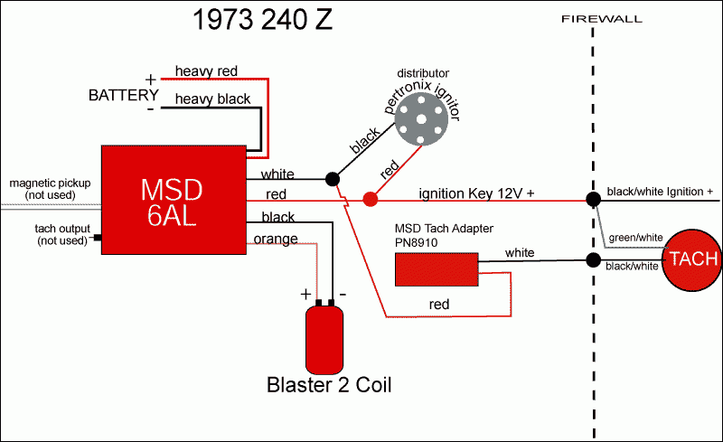
Pertronix Electronic Ignition Wiring Diagram – Let’s first look at the different terminals used on the ignition switch. These are terminals for the Ignition, Coil, or Accessory. Once we know the purpose of each type of terminal, it is possible to identify the parts of the ignition wiring. In addition, we will discuss the function of the Ignition switch and Coil. Then, we’ll talk about the functions of the ignition switch and Coil.
Terminals for ignition switch
An ignition switch has three separate switches that feed the battery’s current to different destinations. The ON/OFF position of the ignition switch is controlled by the third switch, which delivers power to the choke when it’s pushed. Every manufacturer has its unique color-coding system, which we’ll discuss in a subsequent article. OMC utilizes this method. The connector permits the attachment of a speedometer the ignition switch.
While the majority of ignition switch terminals don’t have an original number, they might be equipped with a different number. To ensure that your wires are correctly connected to the switch, it is recommended to check their continuity. A multimeter that is inexpensive can help you do this. Once you’re satisfied about the integrity of your wires, you will be able install the new connector. If your car has an original ignition switch supplied by the factory (or an electrical loom) The wiring loom may differ from that in the car.
First, understand the differences between ACC and auxiliary outputs. The ACC and IGN terminals are the default connections on your ignition switch. the START and IGN terminals are the main connections to the stereo and radio. The ignition switch is the engine’s on/off button. In older vehicles the terminals of the ignition switch are marked with the alphabets “ACC” as well as “ST” (for the individual magnetic wires).
Terminals for coil
The first step to determine the kind of ignition coil is to understand the terms employed. A basic diagram of the wiring will provide you with a range of connections and terminals. Each coil is equipped with a distinct operating voltage. To determine what kind of coil you’ve got first, you need to test the voltage at S1, which is the primary terminal. To determine if the coil is a Type A, C, or B coil, it is recommended to also check the resistance of S1.
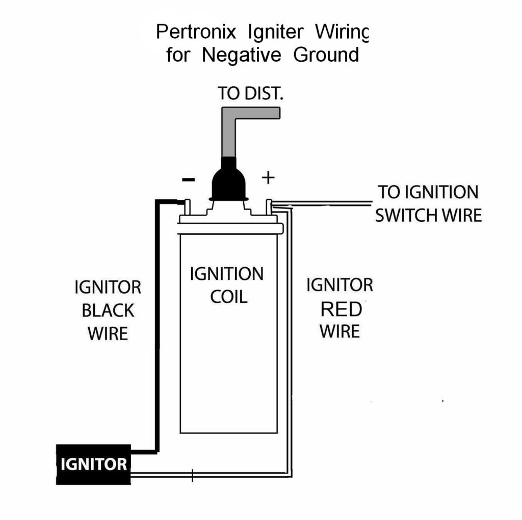
The coil’s low-tension side must be connected to the chassis’ positive. This is the base of the wiring for ignition. The high-tension part provides the spark plugs with positive. To reduce the noise the body of the coil must be connected to chassis. However, it is not required to connect electrically. The wiring diagram for ignition will also indicate the connection of the positive coil’s terminals. In certain instances it is possible to find an ignition coil that is malfunctioning is identified by a scan in an auto parts store.
The black-and-white-striped wire from the harness goes to the negative terminal. Positive terminal receives a white wire that includes a black trace. The black wire is connected to the contact breaker. To confirm the connections, use a paperclip or a pencil to pull them out of the plug housing. Make sure the terminals aren’t bent.
Accessory terminals
Diagrams of the ignition wiring show the wires used to power various parts of the vehicle. Each component is equipped with four distinct colored connections. For accessories, red stands the starter solenoid’s color, yellow for battery, and blue is for accessory. The “IGN” terminal is used to turn on the car and operate the wipers and other operating functions. The diagram shows how you can connect the ACC and ST terminals to the other components.
The terminal called BAT is the location where the battery is. Without the battery the electrical system can not get started. The switch will not turn on if the battery isn’t there. You may refer to the wiring diagram if unsure where your car’s batteries are. The ignition switch is connected to the battery of your car. The BAT terminal is connected with the battery.
Certain ignition switches come with an “accessory” position that permits users to regulate their outputs without needing to utilize the ignition. Some customers prefer to use an auxiliary output that is not connected to the ignition. Use the secondary output by connecting it to the ACC terminal on the switch using the same colors. This feature is convenient, but it has one significant difference. Most ignition switches are designed to display an ACC status when the car’s at either the ACC or START position.
Gallery of Pertronix Electronic Ignition Wiring Diagram

Gallery of Pertronix Electronic Ignition Wiring Diagram


