Pit Bike Ignition Wiring Diagram – We will first examine the various types of terminals on the ignition switch. These include the terminals that are for the Ignition switch, Coil, and Accessory. Once we understand the function of each kind of terminal, we are able to identify the parts of the ignition wiring. Then, we will discuss what functions are available for the Ignition switch, as well as the Coil. After that, we will focus on the accessories terminals.
Terminals for ignition switch
The ignition switch consists of three switches. They are the ones that supply the battery’s power to several locations. The first one supplies power to the choke whenever it is pushed. The second is the switch that controls the ignition’s ON/OFF positions. Each manufacturer has its own color-coding system, which we’ll discuss in a subsequent article. OMC utilizes the same system. The ignition switch also includes a connector for adding the Tachometer.
Although the majority of ignition switch terminals do not have an initial number, they could have a different one. First, check the continuity of each wire to ensure that they are properly connected to the ignition switches. You can check this using an inexpensive multimeter. After you’re satisfied with the quality of the connection, you can place the new connector. The wiring loom used in a factory-supplied ignition system switch is different.
Understanding how ACC outputs connect to the other outputs in your car is vital. The ACC/IGN terminals act as the default connections for the ignition switch. The START/IGN terminals are connected to the stereo or radio. The ignition switch is accountable to turn the car’s engines on and off. The terminals of the ignition switch on older vehicles are marked with the initials “ACC” as well as “ST” (for the individual magneto wires).
Terminals for coil
The terms used to define the model and type of an ignition coil is the first thing. A basic diagram of the wiring will show you a number of connections and terminals. Each coil comes with its own operating voltage. To determine what kind of coil you’ve got the first step is to test the voltage at the S1 primary terminal. S1 should be examined for resistance to identify if the coil belongs to Type A, B, or C.
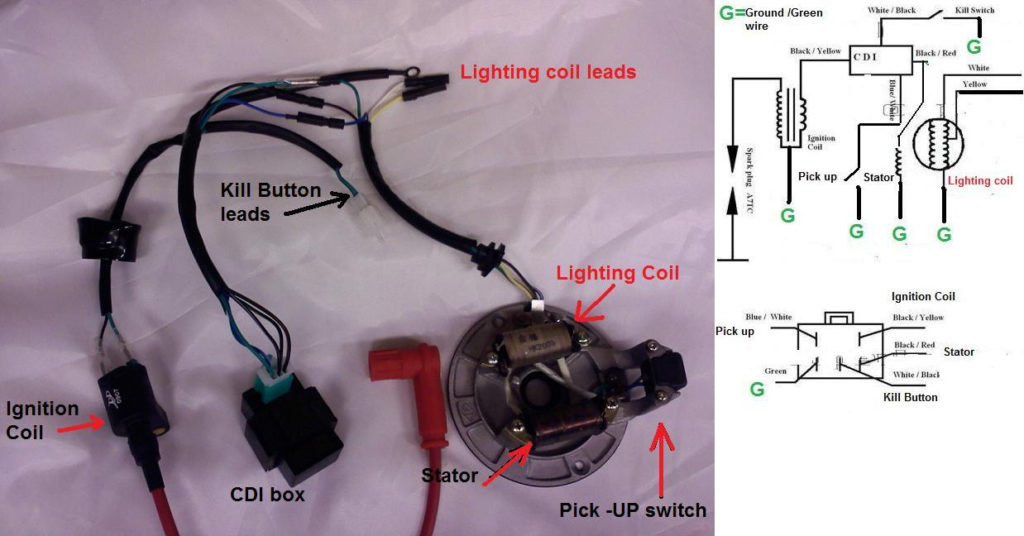
The low-tension coil side must be connected to the chassis’s less. This is what you see on the diagram of wiring. The high tension side provides positive power directly to the spark plugs. To reduce the noise, the coil’s metal body must be connected to the chassis. However, it is not required to connect electrically. A wiring diagram can also illustrate the connection between the positive and negative coils. Sometimes, a check at an auto part store can diagnose a malfunctioning ignition wire.
The black-and-white-striped wire from the harness goes to the negative terminal. The other white wire is black-colored and goes to the negative terminal. The black wire connects to the contact breaker. To verify the wires’ connections, employ a paperclip to lift them from the housing. It is also important to ensure that the terminals aren’t bent.
Accessory terminals
Diagrams of ignition wiring show the different wires that are used to power the car’s various parts. There are typically four terminals with color codes that are connected to each component. Red is used to indicate accessories, yellow the battery, and green the starter solenoid. The “IGN terminal lets you start the car, manage the wipers, or any other operation features. The diagram shows the connection between the ACCas well as ST terminals.
The terminal BAT is where the battery is. The electrical system is not able to begin without the battery. The switch won’t be able to turn on if there is no battery present. If you’re not sure of the exact location where the battery in your car is situated, examine your wiring diagram to see how to locate it. The accessory terminals of your car are connected to the ignition switch, as well as the battery. The BAT terminal is connected to the battery.
Certain ignition switches come with an accessory position where users can modify their outputs and manage them without the need to use the ignition. Some customers prefer to use an auxiliary output independent of the ignition. You can use the additional input by connecting the connector to the ACC terminal. This is a great convenience feature, but there is one differentiator. The majority of ignition switches are set to have an ACC position when the car is in the ACC position, but they’re in the START position when the vehicle is in the IGN position.
Gallery of Pit Bike Ignition Wiring Diagram

Gallery of Pit Bike Ignition Wiring Diagram


