Points Ignition Wiring Diagram – The first step is to take a look at the different types of terminals that are used in the ignition switch. These include the terminals for the Ignition switch, Coil, and Accessory. Once we understand the function of each terminal, we can then identify the parts of the ignition wiring. We will also discuss what functions are available for the Ignition switch, as well as the Coil. Then we’ll proceed to the Accessory Terminals.
Terminals for ignition switch
An ignition switch is composed of three switches. These are responsible for feeding the battery’s energy to various locations. The first switch supplies the choke with power when pushed, and the second is the position of the ignition switch’s ON/OFF. Different manufacturers use different colour-coding systems that correspond to the conductors. OMC follows this system. Connectors can be connected to the ignition switch to add the digital tachometer.
While many ignition switch terminals could not be original, the numbers of the terminals may not be in line with the diagram. Check the continuity of the wires first to ensure that they are correctly plugged in the ignition switch. A cheap multimeter can aid in this. When you’re satisfied with the integrity of your wires, you will be able to install the new connector. If your car is equipped with an original factory-supplied ignition switch (or an electrical loom) The wiring loom will differ from that in your vehicle.
First, understand the differences between the ACC and secondary outputs. The ACC and IGN connectors are the default connections for your ignition switch. The START, IGN, and ACC terminals are the main connections for radios or stereo, the START/IGN connections are the primary ones. The ignition switch is responsible for turning the car’s engine to and off. Older cars have the ignition switch terminals labeled “ACC” or “ST” (for individual magnetowires).
Terminals for Coil
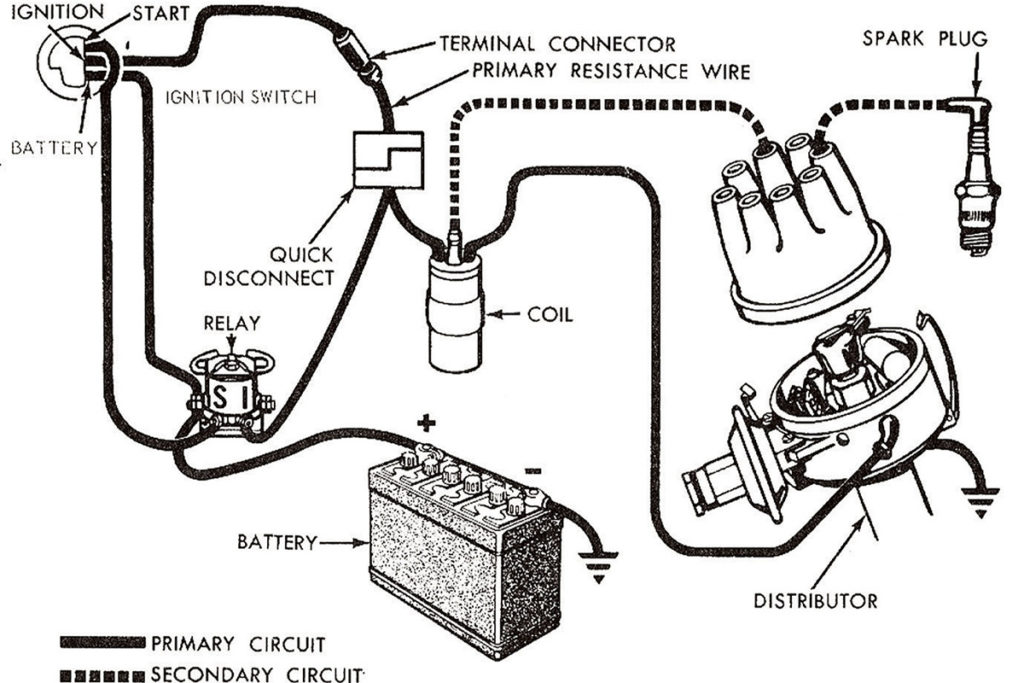
The first step in determining the type of ignition coil is to understand the terminology used. The fundamental diagram of ignition wiring shows a number different connections and terminals. There are two primary and secondary connections. It is essential to identify the type of coil you own by examining the voltage at the primary terminal S1. You should also examine S1 for resistance to determine whether it is an A, B, or C coil.
The chassis’ negative needs to be connected to the low-tension side. This is the ground on the ignition wiring diagram. The high-tension side supplies the positive power direct to the spark plugs. To prevent noise the body of the coil must be connected to chassis. But, it’s not necessary to electrically connect. The diagram of the ignition wiring will also outline the connection of the positive coil terminals. In certain instances it is recommended to conduct a scan at your local auto parts store will be able to diagnose defective ignition coils.
The black-and-white-striped wire from the harness goes to the negative terminal. The positive terminal receives the other white wire, which has an trace in black. The black wire connects to the contactbreaker. You can take the black wire from the housing of the plug with a paper clip if you are unsure about the connections. Make sure that the terminals don’t bend.
Accessory terminals
The ignition wiring diagrams illustrate the different wires that power the various components of the car. There are typically four colored terminals that correspond to the respective component. Red is used to indicate accessories, yellow the battery and green is the starter solenoid. The “IGN” terminal is used to start the car , and also to operate the wipers, as well as other operating functions. The diagram below shows how to connect the ACC terminal and ST terminals to other components.
The terminal BAT is the connection to the battery. The electrical system won’t start if the battery isn’t connected. Additionally, the switch will not turn on without the battery. A wiring diagram can tell you the location of the battery in your car. The ignition switch is linked to the car’s battery. The BAT terminal is connected to the battery.
Certain ignition switches provide an additional “accessory position” which allows users to adjust their outputs independently of the ignition. Customers may want to utilize the auxiliary output in addition to the ignition. The auxiliary output could be utilized by wiring the connector in the same colors as the ignition, and then attaching it to the ACC terminal of the switch. This option is useful, but it has one significant distinction. Most ignition switches are set to be in an ACC position when the vehicle is in the ACC position, while they’re in the START position when the car is in the IGN position.
Gallery of Points Ignition Wiring Diagram
Gallery of Points Ignition Wiring Diagram


