Pollak Marine Ignition Switch Wiring Diagram – In the beginning, we’ll look at the different types of terminals found in the ignition switch. They include terminals for Coil, Ignition Switch, and Accessory. After we’ve identified what these terminals are, we will determine the various components in the ignition wiring. Then, we will discuss the roles of the Ignition switch as well as the Coil. We’ll then turn our attention to the accessory terminals.
Terminals for the ignition switch
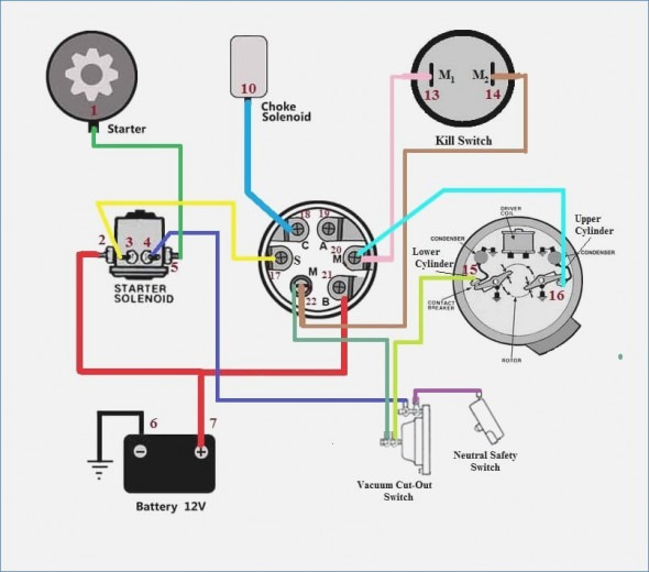
There are three separate switches on an ignition switch that provide the battery’s voltage to various destinations. The first switch powers the choke. The second switch is responsible for the ON/OFF function of the ignition switch. Different manufacturers have distinct colors-coding systems to match the conductors. OMC uses this method. A connector can be added to the ignition switch to connect a digital tachometer.
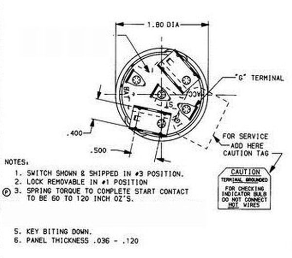
Although some ignition switch terminals might not be authentic, the numbering of each may not match the diagram. Before you plug into the ignition switch ensure that you check the continuity. This can be checked using a cheap multimeter. After you’ve confirmed the continuity of the wires you can then install the connector. If your car is equipped with an original ignition switch supplied by the factory (or a wiring loom) The wiring loom might differ from the one in your car.
First, understand the differences between the ACC and secondary outputs. The ACC and IGN terminals are the default connections on your ignition switch. the START and IGN terminals are the principal connections for radio and stereo. The ignition switch is the one that controls the engine of your car. The terminals on older cars’ ignition switches are labeled by “ACC” and ST (for individual magneto wires).
Terminals for coil
Understanding the terminology utilized is the initial step towards finding out the right kind of ignition coil to choose. You’ll see a number of connections and terminals within a basic ignition wiring schematic which includes two primary and two secondary. Each coil comes with its own operating voltage. To determine the type of coil you have the first step is to check the voltage at S1, which is the primary terminal. Also, you should examine S1 for resistance to determine whether it is a Type A B, C, or coil.
The coil’s low-tension end is to be connected to the chassis positive. This is what’s called the ground in the wiring diagram for ignition. The high-tension part supplies the spark plugs with positive. The aluminum body of the coil has to be connected to the chassis for suppression but isn’t required. There are also connections between the positive and negative coil terminals on the ignition wiring diagram. In certain instances, you’ll find that the ignition coil is damaged and can be diagnosed with a scan in an auto parts store.
The black-and-white-striped wire from the harness goes to the negative terminal. The terminal for the negative is served by the black trace that’s connected to the white wire. The black wire is connected to the contact breaker. You can take the black wire from the housing of the plug using a paper clip if you are unsure about the connection. It is also important to make sure that the connections aren’t bent.
Accessory Terminals
The wiring diagrams of the ignition illustrate the various wires that are used to power various components of the vehicle. There are usually four colored terminals that correspond to the component. The red color represents accessories, yellow is for the battery and green is for the solenoid for starters. The “IGN terminal” is used to power the wipers and other operating features. This diagram demonstrates how to connect ACC and ST terminals with the rest of the components.
The terminal BAT connects the battery to the charger. Without the battery the electrical system can not start. Additionally, the switch won’t begin to turn on. To find the battery in your car look over your wiring diagram. The ignition switch is connected to the battery of your car. The BAT terminal connects to the battery.
Some ignition switches feature an additional “accessory” position, where users can manage their outputs with no ignition. Sometimes, customers want to use an auxiliary output that is not connected to the ignition. You can utilize the secondary input by connecting the connector to the ACC terminal. This is a great feature, however there’s one important distinction. Most ignition switches will have an ACC position if the car is in the ACC, but they’ll be at the START position when the vehicle is in IGN.
Gallery of Pollak Marine Ignition Switch Wiring Diagram
Gallery of Pollak Marine Ignition Switch Wiring Diagram


