Porsche 911 Ignition Switch Wiring Diagram – We will first take a look at the various kinds of terminals found on the ignition switch. These include terminals for Coil, Ignition Switch, and Accessory. Once we have identified what these terminals do then we can determine the various components in the ignition wiring. We’ll also discuss the functions of both the Ignition Switch and the Coil. After that we will proceed to the Accessory Terminals.
Terminals for ignition switches
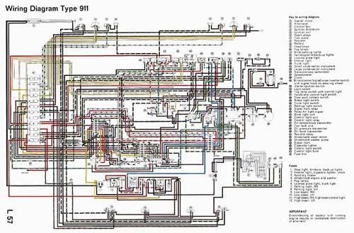
An ignition switch is made up of three switches. These are responsible for feeding the battery’s power to several destinations. The first switch is utilized to power the choke through pushing it, while the second is for the ON/OFF setting. Every manufacturer has its unique color-coding system, which we’ll go over in a separate article. OMC utilizes this method. The adapter is attached to the ignition switch that allows the addition of the tachometer.
While most ignition switch terminals can be duplicated, the numbers might not match the diagram. Check the continuity of all the wires to ensure that they are properly plugged into the ignition switches. You can do this with a simple multimeter. When you’re satisfied with the continuity of your wires, you’ll be able install the new connector. If your car is equipped with an original factory-supplied ignition switch (or an electrical loom) the wiring loom will differ from that in the car.
Before connecting the ACC outputs to your car’s auxiliary outputs It is essential to know the fundamentals of these connections. The ACC and IGN connectors are the default connections for the ignition switch. The START, IGN, and ACC terminals are the main connections for radios or stereo, the START/IGN terminals are the most important ones. The ignition switch is the one that turns the car’s engine on and off. On older cars the ignition switch’s terminals are identified with the initials “ACC” as well as “ST” (for the individual magnet wires).
Terminals for coil
Understanding the terminology is the initial step to knowing what type of ignition coil you have. The diagram of the basic ignition wiring shows a number different connections and terminals. There are two primary and secondary connections. Each coil is equipped with a distinct operating voltage. To determine which type of coil you have first, you need to determine the voltage at S1, which is the primary terminal. S1 should be tested for resistance in order to determine if the coil is type A, B or C.
The lower-tension side of the coil should be connected to the chassis”negative. This is also the ground in the ignition wiring diagram. The high-tension part is a positive connection to the sparkplugs. The body of the coil has to connect to the chassis to prevent it from being smothered but is not electrically required. The diagram for the ignition wiring will also demonstrate the connection of the negative and positive coil terminals. Sometimes, a malfunctioning ignition coil can be identified through a scan performed in an auto parts shop.
The black-and-white-striped wire from the harness goes to the negative terminal. The positive terminal is connected to the white wire with the black trace. The black wire connects with the contact breaker. To confirm the connections, employ a paperclip, or a pencil to lift them out from the plug housing. It is also important to make sure that the terminals aren’t bent.
Accessory terminals
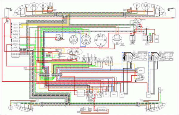
The wiring diagrams of the ignition illustrate the different wires used to are used to power various components of the vehicle. There are usually four terminals with color codes that are connected to the respective component. For accessories, red is the starter solenoid’s color, blue for battery, and blue for accessory. The “IGN terminal” is used to power the wipers along with other operational features. The diagram shows how to connect the ACC and ST terminals to the other components.
The battery is connected to the terminal whose name is BAT. The battery is essential for the electrical system to start. Additionally the switch won’t come on. You can refer to your wiring diagram if unsure where your car’s batteries are located. Your car’s accessory terminals connect to the ignition switch and the battery. The BAT terminal is connected to the battery.
Some ignition switches feature an additional “accessory” location, which allows users can control their outputs without using the ignition. Users may wish to utilize the auxiliary output in addition to the ignition. To make use of the auxiliary output, wire the connector with identical colors to the ignition, connecting it to the ACC terminal on the switch. This is a great convenience feature, but there is one differentiator. Most ignition switches will be in an ACC position when the vehicle is in ACC however, they’ll be at the START position if the car is in IGN.
Gallery of Porsche 911 Ignition Switch Wiring Diagram
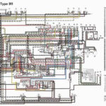
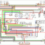
Gallery of Porsche 911 Ignition Switch Wiring Diagram


