Revtech Ignition Wiring Diagram – First, let’s take a look at the different types of terminals on the ignition switch. These include the terminals that are for the Ignition switch, Coil, and Accessory. After we’ve identified which terminals are used then we can determine the various components of the Revtech Ignition Wiring Diagram. In addition, we will discuss the roles of the Ignition switch and Coil. After that, we’ll turn our attention to the Accessory terminals.
The ignition switch’s terminals
Three switches can be found on the ignition switch. Each of the three switches feeds the battery’s voltage to several different locations. The first switch is the one that supplies power to the choke and the third switch toggles the on/off state of the switch. Different manufacturers have their own color-coding system for the different conductors, which is documented in another article. OMC utilizes this method. There is a connector inside the ignition switch to allow attaching an tachometer.
Although the majority of ignition switch terminals don’t have an original number, they may have a different one. Check the continuity of the wires first to make sure they are correctly plugged in the ignition switch. This can be done with a simple multimeter. Once you are satisfied that all wires are in good order, you can attach the new connector. If you have an ignition switch supplied by the manufacturer, the wiring loom is distinct from the one that is used in your vehicle.
You must first understand the ways in which the ACC outputs and the auxiliary outputs function to connect them. The ACC/IGN terminals function as the default connections on the ignition switch. The START/IGN terminals connect to the radio or stereo. The ignition switch’s function is for turning the car’s engine on and off. Older cars are equipped with ignition switch terminals marked “ACC” or “ST” (for individual magnetowires).
Terminals for coil
The first step to determine the type of ignition coil is to understand the terminology used. You will see several connections and terminals on a basic ignition wiring schematic that include two primary as well as two secondary. The coils are equipped with a particular operating voltage. The initial method of determining what type you’ve got is to check the voltage at S1, the main terminal. To determine if it is an A, C, or B coil, you should also test S1’s resistance.
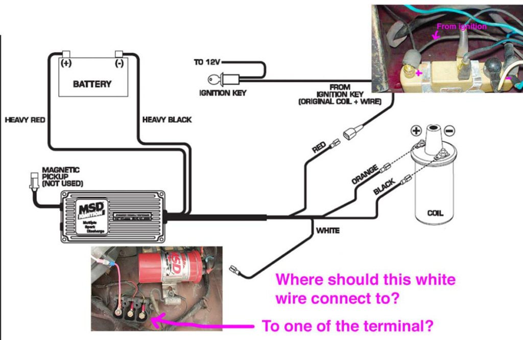
The low-tension end of the coil must be connected to the chassis the negative. This is what is known as the ground for the wiring for ignition. The high-tension end is a positive connection to the sparkplugs. To reduce the noise, the coil’s metal body must be connected to the chassis. But, it’s not necessary to connect the coil electrically. The diagram of the ignition wiring will also show the connection of the positive coil terminals. In certain instances, you’ll find that an ignition coil that is malfunctioning is identified by scanning at an auto parts store.
The black-and-white-striped wire from the harness goes to the negative terminal. The negative terminal is served by the black trace that’s joined to the white wire. The black wire connects to the contact breaker. You can take the black wire from the housing of the plug using a paper clip in case you are uncertain about the connections. Make sure you don’t bend the connectors.
Accessory terminals
Diagrams of the ignition wiring illustrate the wiring used to supply power to different parts of the car. Each part has four distinct connections that are color coded. Red stands for accessories, yellow represents the battery, and green for the starter solenoid. The “IGN” terminal is used for starting the car, controlling the wipers and other functions. The diagram illustrates how you can connect ACC or ST terminals as well as the rest.
The terminal BAT connects the battery to the charger. Without the battery the electrical system will not begin. The switch won’t be able to turn on if there is no battery there. To find the battery in your car, check your wiring diagram. The ignition switch and the battery are connected via accessory terminals. The BAT Terminal is connected to the battery.
Some ignition switches feature an “accessory” position that allows users to regulate their outputs without needing to utilize the ignition. Some customers might want to utilize the auxiliary output separately from the ignition. The auxiliary output can be connected to connect the connector with the same colors as the ignition, and then attaching it to the ACC terminal of the switch. This is a great convenience feature, but there is one distinction. The majority of ignition switches are set up to display an ACC status when the vehicle is at either the ACC or START positions.
Gallery of Revtech Ignition Wiring Diagram
Gallery of Revtech Ignition Wiring Diagram


