Rotax 912 Ignition Wiring Diagram – Let’s start by looking at the different types of terminals on an ignition switch. These terminals serve for the Ignition button, Coil and Accessory. Once we know the terminals that are utilized and which ones are not, we can determine the various components of the Rotax 912 Ignition Wiring Diagram. We will also cover the functions of both the Ignition Switch and Coil. Following that, we will proceed to the Accessory Terminals.
Terminals of ignition switch
The ignition switch is comprised of three separate switches that feed the battery’s current to different locations. The first is used to drive the choke through pushing it, and the second is for the ON/OFF position. Each manufacturer has their own color-coding system, which we’ll go over in a separate article. OMC utilizes the same system. The ignition switch also includes a connector for adding an timer.
While the majority of the ignition switch terminals are not authentic, the numbering of each may not match the diagram. Check the continuity of the wires to ensure that they are plugged into the correct ignition switch. A simple multimeter will help you do this. When you’re satisfied with the integrity of your wires, you will be able to connect the new connector. The wiring loom of an ignition switch that is supplied by the factory will be different from the one that you have in your car.
It is important to know the differences between the ACC and the auxiliary outputs. The ACC and IGN terminals are the default connections on the ignition switch. the START and IGN terminals are the primary connections for radio and stereo. The ignition switch’s function is to turn the engine of your car on and off. The terminals of older cars ignition switches are identified by “ACC” and ST (for the individual magneto wires).
Terminals for coil
Understanding the terminology used is the first step in determining what type of ignition coil. A simple diagram of the wiring will reveal a variety of terminals and connections which include two primary terminals and two secondary. Each coil is equipped with a distinct operating voltage. To determine the type of coil you’ve got, the first step is to check the voltage at S1, which is the primary terminal. S1 should be tested for resistance in order to identify if the coil belongs to type A, B and/or C.
The lower-tension side of the coil needs to be connected to the chassis”negative. This is also the ground in the wiring diagram for ignition. The high-tension end supplies positive direct to the sparkplugs. The aluminum body of the coil needs to be connected to the chassis for suppression, but it isn’t electrically required. The wiring diagram of the ignition will demonstrate how to connect the two terminals of the positive or negative coils. In certain cases it is recommended to conduct a scan at your local auto parts store will help identify malfunctioning ignition coils.
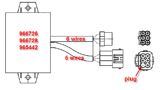
The black-and-white-striped wire from the harness goes to the negative terminal. The positive terminal also gets the white wire that has a black trace. The contact breaker is linked to the black wire. If you’re unsure of the connections between both, you can use an old paper clip to take them from the plug housing. Make sure you don’t bend the connectors.
Accessory terminals
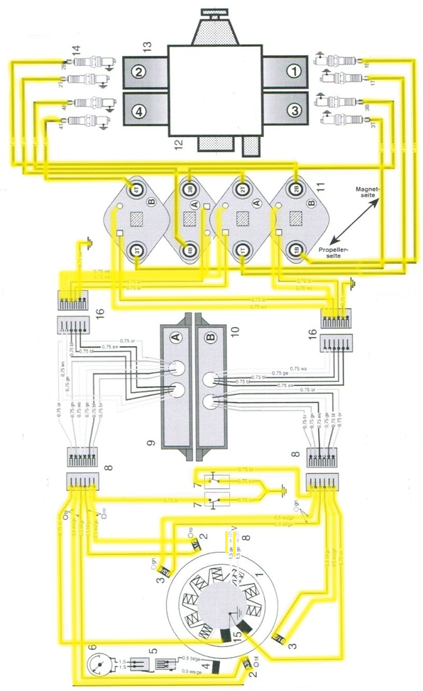
Diagrams of ignition wiring show the wires that provide power to various components of the vehicle. Each part has four distinct color-coded connections. Red stands for accessories, yellow represents the battery, and green for the solenoid for starters. The “IGN” terminal is utilized to turn on the car, operate the wipers, as well as other functions. The diagram below illustrates how to connect the ACC terminal and ST terminals to the other components.
The terminal called BAT is where the battery is connected. The battery is vital for the electrical system to begin. The switch won’t be able to turn on if the battery isn’t present. If you’re not sure the exact location where the battery in your car is situated, look at your wiring diagram to figure out the best way to find it. The accessory terminals in your car are connected to the ignition switch as well as the battery. The BAT terminal is connected with the battery.
Certain ignition switches have an accessory setting where users can alter their outputs and control them without needing to use the ignition. Some customers might want to use the auxiliary input separately from the ignition. To allow the auxiliary output to be used, plug in the connector to the same shade as the ignition. Then connect it with the ACC end of the switch. This is a useful feature, however there’s one important distinction. The majority of ignition switches have an ACC position when the vehicle is in the ACC however, they’ll be at the START position if the car is in IGN.
Gallery of Rotax 912 Ignition Wiring Diagram
Gallery of Rotax 912 Ignition Wiring Diagram


