Rzr 170 Ignition Switch Wiring Diagram – First, we will examine the different types of terminals for the ignition switch. The terminals are the Ignition switch, the Coil as well as the Accessory. Once we know the purpose of these terminals are for, we will proceed to determine the various parts of the Rzr 170 Ignition Switch Wiring Diagram. In addition, we will discuss the different functions of the Ignition Switch and Coil. Then, we’ll focus to the accessory terminals.
The terminals of the ignition switch
An ignition switch contains three switches that supply the battery’s current to different destinations. The first switch supplies power to the choke when it is pushed. The third is the switch that controls the ignition’s ON/OFF positions. Different manufacturers use different color-coding methods to identify different conductors. We will cover this in another article. OMC uses the same method. The connector allows for the attachment of a speedometer to the ignition switch.
Although the majority of ignition switch terminals can be duplicated, the numbers might not be consistent with the diagram. To ensure that your wires are correctly plugged in to the ignition switch you must verify their continuity. This can be done with an inexpensive multimeter. After you’re satisfied with the connection it’s time to connect the new connector. The wiring loom of an ignition switch that is supplied by the factory will be different from the one in your vehicle.
Understanding how ACC outputs connect to the other outputs of your car is vital. The ACC and IGN connectors are the default connections for the ignition switch. The START, IGN, and ACC terminals are the main connections for radios or stereo, the START/IGN connections are the most important ones. The ignition switch is responsible to turn the engine of your car on and off. Older cars are identified with the initials “ACC”, “ST”, (for individual magneto cables) at their ignition switch terminals.
Terminals for Coil
The terms used to define the type and model of the ignition coil is the most important thing. In a typical diagram of the wiring for ignition you’ll see various terminals and connections, including two primary and two secondary. The coils have a specific operating voltage, and the first step in determining which type you have will involve testing the voltage on S1, the primary terminal. S1 should be examined for resistance to determine if the coil is type A, B and/or C.
The low-tension coil side must be connected to the chassis’s plus. This is what’s called the ground on the wiring diagram for ignition. The high-tension part supplies positive direct to the sparkplugs. For suppression purposes the body of the coil is required to be connected to the chassis. It is not necessary to electrically connect. The wiring diagram for ignition will also indicate the connection of the positive coil terminals. Sometimes, a damaged ignition coil can be detected through a scan performed in an auto parts shop.
The black-and-white-striped wire from the harness goes to the negative terminal. The positive terminal is connected to the white wire with the trace in black. The contact breaker is connected to the black wire. If you’re not sure about the connection between both, you can use an old paper clip to take them from the housing of the plug. Make sure that the terminals do not bend.
Accessory terminals
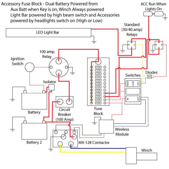
The ignition wiring diagrams show the various wires utilized to power the different components. In general, there are four different colors-coded terminals that are used for each component. Red is for accessories while yellow is the battery, while green is the starter solenoid. The “IGN” terminal can be used to start the car, operate the wipers and other features. The following diagram illustrates how to connect the ACC terminal as well as the ST terminals to other components.
The battery is connected to the terminal named BAT. The electrical system can’t be started without the battery. The switch also won’t start without the battery. To find your car’s battery examine the wiring diagram. The ignition switch and battery are connected via accessory terminals. The BAT terminal is connected with the battery.
Some ignition switches include an additional position in which users can alter their outputs and control them without the need to use the ignition. Users may wish to utilize the auxiliary output in addition to the ignition. You can use the additional output by connecting it to an ACC terminal on your switch with the same colors. This is a useful feature, but there is one important distinction. The majority of ignition switches are set up to show an ACC status when the car’s at the ACC or START position.
Gallery of Rzr 170 Ignition Switch Wiring Diagram
Gallery of Rzr 170 Ignition Switch Wiring Diagram


