S10 Ignition Switch Wiring Diagram – Let’s begin by looking at the different types terminals found on the ignition switch. The terminals are the Ignition switch and Coil along with the Accessory. After we’ve identified the purpose of the terminals we can recognize the various parts of the ignition wiring. We’ll also go over the roles of the Ignition switch and Coil. We will then discuss the functions of the Ignition switch and Coil.
Terminals for the ignition switch
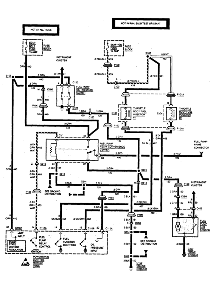
There are three different switches on an ignition switch, which transmit the battery’s current voltage to a variety of destinations. The first switch supplies power to the choke, while the second toggles the ON/OFF state of the switch. Different manufacturers utilize their own color-coding method for different conductors that is described in a separate article. OMC uses this system. The ignition switch is also equipped with a connector for adding the timer.
Although the majority of ignition switch terminals may not be authentic, the numbering of each may not match the diagram. Verify the continuity of the wires first to ensure they’re properly connected to the ignition switch. This can be done with a cheap multimeter. After you’re happy with the continuity of the wires, you can connect the new connector. The wiring loom used in an ignition system switch that is supplied by the manufacturer differs.
For connecting the ACC outputs to the auxiliary outputs of your car, you need to understand the way these two connections function. The ACC terminals as well as the IGN terminals serve as the default connections to your ignition switch. The START and IGN connections are the primary connections for stereo and radio. The ignition switch controls the car’s engine. Older cars are equipped with ignition switch terminals marked “ACC” or “ST” (for individual magnetowires).
Terminals for coil
The first step to determine the type of ignition coil is to know the terms that is used. A simple diagram of the wiring will show a variety of terminals and connections, comprising two primary and two secondary. Each coil comes with its own operating voltage. To determine the type of coil you’ve got, the first step is to test the voltage at the S1 primary terminal. S1 should be checked for resistance to determine if the coil is Type A, B, or C.
The coil’s low-tension end must be connected with the chassis positively. This is the ground in the diagram of the ignition wiring. The high-tension side provides the spark plugs with positive. The aluminum body of the coil has to be connected to the chassis to prevent it from being smothered but isn’t required. The diagram of the ignition wiring will also reveal the connection of the negative and positive coil’s terminals. Sometimes, an inspection at an auto parts store could detect a defective ignition wire.
The black-and-white-striped wire from the harness goes to the negative terminal. Positive terminal receives a white wire that has a black trace. The black wire connects to the contact breaker. You can examine the connections with a pencil to take the wires out of the housing. Also, make sure that the connections aren’t bent.
Accessory terminals
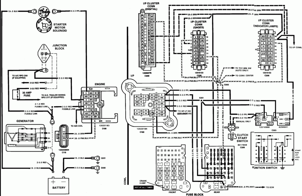
Ignition wiring diagrams show the different wires that are used to power the car’s various parts. In general there are four colors-coded terminals that are used for each component. Red is used for accessories, yellow is for the battery, and green is the solenoid for starters. The “IGN” terminal is used to turn on the car and operate the wipers and other operating functions. The diagram demonstrates how to connect the ACC and ST terminals to the rest of the components.
The terminal referred to as BAT is the place where the battery is. The battery is vital to allow the electrical system to begin. A dead battery could make the switch stop turning on. If you’re not sure the location of your car’s battery situated, examine your wiring diagram to see where it is. The ignition switch is linked to the car’s battery. The BAT terminal is connected to the battery.
Some ignition switches include an accessory setting where users can alter their outputs as well as control them without the need to use the ignition. Sometimes, customers want to make use of an additional output that is not connected to the ignition. You can utilize the auxiliary input by connecting it to the ACC terminal. Although this is a great feature, there’s something to be aware of. The majority of ignition switches have an ACC position when the vehicle is in ACC however, they will be in the START position when the vehicle is in IGN.
Gallery of S10 Ignition Switch Wiring Diagram
Gallery of S10 Ignition Switch Wiring Diagram


