S13 Ignition Switch Wiring Diagram – Let’s begin by looking at the different kinds of terminals that are found on the ignition switch. They are the terminals used for Coil, Ignition Switch, and Accessory. Once we have identified the terminals that are utilized and which ones are not, we can identify the different components of the S13 Ignition Switch Wiring Diagram. We will also discuss the roles of the Ignition switch, as well as the Coil. We will then concentrate on the accessory terminals.
The terminals are for ignition switches.
An ignition switch has three switches. They feed the voltage of the battery to different locations. The ON/OFF state of the switch that controls the ignition is managed by the first switch, which provides the choke with power when it’s pulled. Different manufacturers utilize their own color-coding method for different conductors which is explained in a different article. OMC follows this method. The adapter is attached to the ignition switch to allow the installation of an tonometer.
While most ignition switch terminals aren’t original, the numbering for each might not be consistent with the diagram. To ensure that the wires are correctly connected to the ignition switch it is recommended to check their continuity. This can be checked using a simple multimeter. When you’re satisfied that the wires are running in good harmony, you can attach the new connector. The wiring loom of an ignition system switch that is supplied by the manufacturer is distinct.
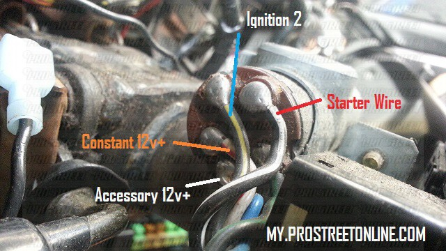
Before connecting the ACC outputs to your car’s auxiliary outputs it is crucial to know the fundamentals of these connections. The ACC, IGN and START terminals are the primary connections to the ignition switch. They also serve as the primary connections to the radio and stereo. The ignition switch controls the car’s engine. The ignition switch terminals on older cars are identified with the initials “ACC” and “ST” (for individual magneto wires).
Terminals for coil
The first step in determining the kind of ignition coil is to comprehend the terminology that is used. In a typical ignition wiring diagram you’ll see various terminals and connections, including two primary and two secondary. The coils have a specific operating voltage. The initial step in determining which type you’ve got is to check the voltage on S1, the main terminal. To determine whether it’s a Type A, C or B coil it is recommended to also test S1’s resistance.
The chassis’ negative end should be connected to to the coil’s lower-tension end. It is also the ground in the diagram of ignition wiring. The high-tension component supplies the spark plugs with positive. For suppression purposes the coil’s body metal is required to be connected to the chassis. It is not required to use electricity. The wiring diagram for ignition will also show the connections of the positive coil terminals. Sometimes, an inspection at an auto parts shop can diagnose a malfunctioning ignition wire.
The black-and-white-striped wire from the harness goes to the negative terminal. The white wire is the other one. It is black with a trace on it, and it connects to the positive terminal. The black wire connects to the contactbreaker. If you’re unsure of the connection between the twowires, use the clip of a paperclip to remove them from the housing of the plug. Also, make sure to ensure that the terminals aren’t bent.
Accessory terminals
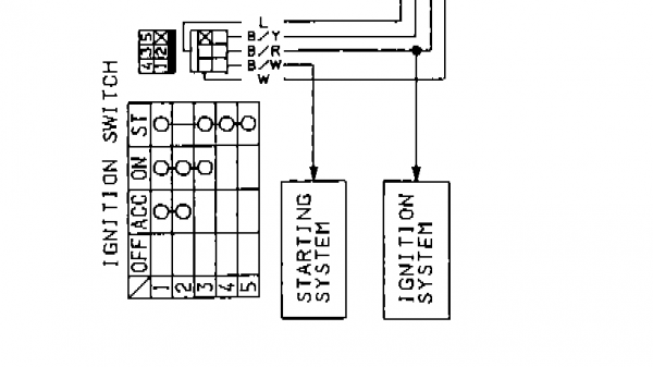
The ignition wiring diagrams illustrate the different wires that are used to power the car’s various components. There are generally four terminals with color codes that are connected to the respective component. The accessories are red, the battery is yellow, the starter solenoid is green. The “IGN” terminal can be used to turn on the car, control the wipers and other features. The diagram below shows how to connect the ACC terminal as well as the ST terminals to various components.
The terminal referred to as BAT is where the battery is connected. The electrical system can’t be started without the battery. The switch won’t turn off if the battery isn’t there. A wiring diagram can inform you the location of the battery of your car. The accessory terminals on your car connect to the battery and the ignition switch. The BAT terminal is connected to the battery.
Certain ignition switches provide the option of an “accessory position” that lets users adjust their outputs independently of the ignition. Sometimes, customers want to use the auxiliary output separately from the ignition. Make use of the additional output by connecting it to the ACC terminal on the switch that has the same color. While this is an excellent feature, there is one crucial distinction. Most ignition switches are configured to be in an ACC position when the car is in the ACC position, but they’re in the START position when the car is in the IGN position.
Gallery of S13 Ignition Switch Wiring Diagram
Gallery of S13 Ignition Switch Wiring Diagram


