Schematic 5 Prong Ignition Switch Wiring Diagram – Let’s begin by examining the different types and purposes of the terminals in the ignition switches. These include the terminals for the Ignition switch, Coil, and Accessory. Once we know the terminals used and which ones are not, we can determine the various components of the Schematic 5 Prong Ignition Switch Wiring Diagram. We will also discuss the functions for the Ignition switch, as well as the Coil. Following that, we will proceed to the Accessory Terminals.
Terminals for ignition switches
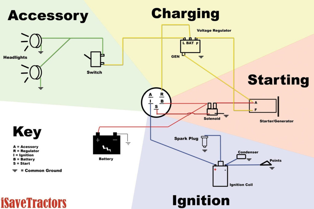
An ignition switch is composed of three switches. These are the ones that supply the battery’s energy to various destinations. The ON/OFF state of the ignition switch is controlled by the second switch, which delivers power to the choke when it’s pulled. Each manufacturer has its own color-coding system, which we will discuss in another article. OMC utilizes this system. Connectors can be connected to the ignition switch in order to include an electronic tachometer.
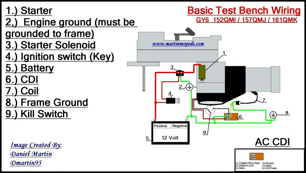
Although the majority of ignition switch terminals aren’t authentic, the numbering of each may not match the diagram. It is important to first verify the electrical continuity to determine if they’re plugged into the ignition switch in the correct way. A multimeter is a good tool to test the continuity. When you’re happy with the quality of the connection it’s time to connect the new connector. If your car has an ignition switch that is installed, the wiring diagram will differ.
Knowing how the ACC outputs are connected to the other outputs in your car is vital. The ACC terminals as well as the IGN terminals function as the standard connections for your ignition switch. The START and IGN connections are the most important connections for radio and stereo. The ignition switch operates the engine’s switch to turn off or on. The terminals on older cars ignition switches are identified with “ACC” and ST (for specific magneto wires).
Terminals for coil
The language used to decide the model and type of the ignition coil is the most important thing. You’ll see a number of connections and terminals on an ignition wiring schematic, including two primary, as well as two secondary. You need to determine the type of coil that you own by examining the voltage at the primary terminal, S1. To determine whether it’s an A, C or B coil you must also check the resistance of S1.
The coil’s low-tension side should be connected at the chassis’ minus. This is the ground on the ignition wiring diagram. The high-tension supply delivers the spark plugs with positive electricity directly. For suppression purposes the coil’s metal body must be connected with the chassis. This is not necessary for electrical use. The wiring diagram of the ignition will explain how to connect the terminals of either the negative or positive coils. In certain cases, a scan at your local auto parts shop will be able to diagnose defective ignition coils.
The black-and-white-striped wire from the harness goes to the negative terminal. The terminal that is negative is served by the black trace joined to the white wire. The black wire is connected to the contact breaker. It is possible to check the connections using a paperclip to pull the wires out of the housing. You should also check to see that the terminals aren’t bent.
Accessory terminals
Ignition wiring diagrams show the different wires that are used to power the car’s various components. There are typically four different colored terminus lines for each component. Accessories are red while the battery is yellow and the starter solenoid green. The “IGN terminal lets you start the car, control the wipers or other functions. This diagram shows how to connect ACC and ST terminals to the other components.
The terminal referred to as BAT is the place where the battery is. Without the battery the electrical system can not get started. Also, the switch won’t be able to turn on without the battery. You may refer to the wiring diagram if you’re not sure where the batteries of your car are. Your car’s accessory terminals are connected to the ignition switch, as well as the battery. The BAT terminal is connected to the battery.
Certain ignition switches provide an additional “accessory position” which allows users to alter their outputs without the ignition. Some customers might want to utilize the auxiliary output separately from the ignition. To use the auxiliary output, connect the connector with the same colors as ignition, and connect it to the ACC terminal on the switch. This is a great feature, however there’s one important difference. Most ignition switches will have an ACC position if the car is in the ACC however they’ll be at the START position if the vehicle is in IGN.
Gallery of Schematic 5 Prong Ignition Switch Wiring Diagram
Gallery of Schematic 5 Prong Ignition Switch Wiring Diagram


