Scooter Ignition Switch Wiring Diagram – First, we will examine the various types of terminals found on the ignition switch. The terminals are the Ignition switch, the Coil as well as the Accessory. After we’ve identified the purpose of these terminals, we will be able to recognize the various parts of the ignition wiring. We’ll also discuss the functions and the Coil. The next step is to focus to the accessory terminals.
Terminals of ignition switch
An ignition switch has three separate switches that feed the battery’s current to different locations. The ON/OFF position of the ignition switch is controlled by the third switch, which delivers the choke with power when it is pushed. Different manufacturers employ various color codes for the different conductors. This is explained in a different article. OMC uses this method. A connector is also included in the ignition switch for attaching a tachometer.
Even though most ignition switch terminals don’t have an initial number, they could have a different one. To make sure that your wires are plugged in to the ignition switch, it is recommended to check their continuity. This can be checked using a cheap multimeter. After you’ve confirmed the continuity of the wires you can connect the connector. The wiring loom in the ignition system switch supplied by the manufacturer differs.
In order to connect the ACC outputs to the auxiliary outputs on your car, you need to understand the way these two connections function. The ACC and IGN terminals are the default connection on your ignition switch, and the START and IGN terminals are the main connections to the radio and stereo. The ignition switch is responsible to turn the car’s engines on and off. Older vehicles have ignition switch’s terminals that are labeled “ACC” or “ST” (for individual magnetowires).
Terminals for coil
Understanding the terms is the first step towards determining which type of ignition coil you own. In a simple ignition wiring diagram there are several different terminals and connections, including two primary and two secondary. Each coil operates at a specific voltage. The first step in determining which kind you’re dealing with is to test the voltage of S1 or the primary terminal. S1 should also be checked for resistance to determine if the coil is a Type B, B or an A coil.
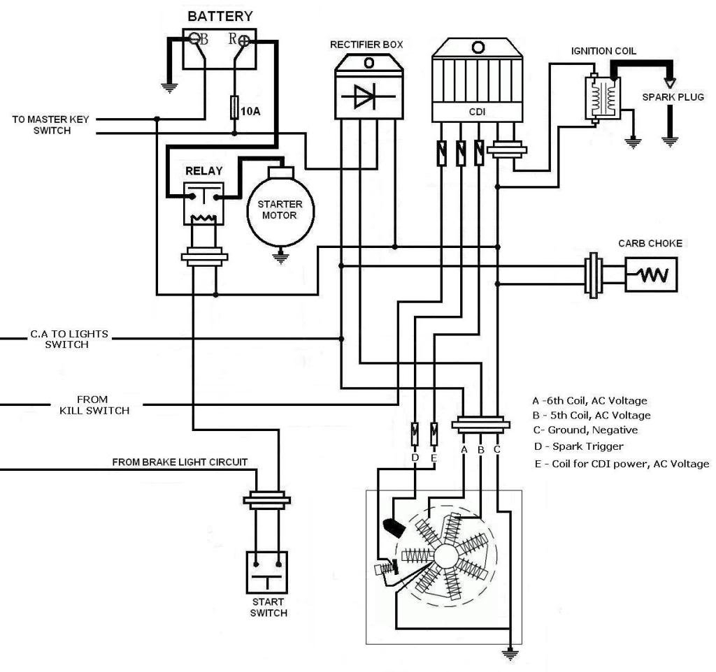
The coil’s low-tension side should be connected at the chassis’ less. This is the base of the wiring for ignition. The high-tension component supplies the spark plugs with positive. The metal body of the coil needs to connect to the chassis to prevent it from being smothered but is not electrically essential. A wiring diagram can also depict the connection between positive and negative coils. Sometimes, a malfunctioning ignition coil can be identified by a scan done in an auto parts shop.
The black-and-white-striped wire from the harness goes to the negative terminal. The white wire is the other one. It has a black trace, and it connects to the positive terminal. The black wire connects to the contact breaker. You can check the connections with a pencil to pull the wires out of the housing. It is also important to see that the terminals aren’t bent.
Accessory Terminals
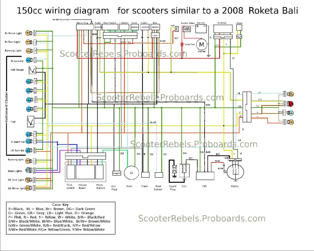
Diagrams of ignition wiring illustrate the wires that are used to power the vehicle’s electrical supply. Each component has four distinct colored connections. The red color is for accessories, yellow is the battery and green is the starter solenoid. The “IGN” terminal can be utilized to turn on the car, operate the wipers and other functions. The diagram shows how to connect ACC or ST terminals and the rest.
The terminal BAT is the connection for the battery. The battery is necessary for the electrical system to get started. A dead battery can make the switch not turn on. A wiring diagram can show you the location of the battery in your car. Your car’s accessory terminals are connected to the ignition switch and the battery. The BAT Terminal is connected to the battery.
Some ignition switches feature an additional “accessory” position, where users can manage their outputs without the ignition. Sometimes, customers wish to use the auxiliary output separately from the ignition. You can use the secondary input by connecting it to the ACC terminal. This feature of convenience is fantastic however, there’s one difference. Many ignition switches can be programmed to have an ACC position once the car has moved into the ACC position. They’ll also be in START mode once the vehicle is moved into the IGN position.
Gallery of Scooter Ignition Switch Wiring Diagram

Gallery of Scooter Ignition Switch Wiring Diagram


