S&s Ist Ignition Wiring Diagram – Let’s first look at the different terminals on the ignition switch. These terminals are for the Ignition button, Coil and Accessory. Once we have identified the purpose of these terminals and what they do, we can then identify the different parts in the ignition wiring. Then, we will discuss the functions as well as the Coil. Then, we will turn our attention towards the accessories terminals.
Terminals for ignition switches
There are three separate switches in an ignition switch, which transmit the battery’s current voltage to several different destinations. The first switch supplies power to the choke when pushed, and the second is the switch that controls the ignition’s ON/OFF positions. Different manufacturers have their own color-coding system for the various conductors, which is documented in another article. OMC follows this approach. The ignition switch also includes an adapter for the addition of an timer.
While most ignition switch terminals may not be authentic, the numbering of each may not match the diagram. Check the continuity of all the wires to make sure they’re properly plugged into the ignition switches. A multimeter that is inexpensive can aid in this. After you have verified that the wires are in good condition, you can connect the connector. The wiring loom for an ignition switch that is supplied by the manufacturer will differ from the one you have in your car.
Before you can connect the ACC outputs to your car’s auxiliary outputs it is crucial to understand the basics of these connections. The ACC and IGN terminals are the default connections on your ignition switch, and the START and IGN terminals are the primary connections for radio and stereo. The ignition switch operates the engine’s switch to turn off or on. The terminals of older cars’ ignition switches are labeled by “ACC” and ST (for the individual magneto wires).
Terminals for coil
Understanding the terminology used is the initial step in determining what kind of ignition coil to choose. An ignition wiring diagram will reveal a variety of terminals and connections, which include two primary terminals and two secondary. The coils come with a distinct operating voltage, and the first step to determine which one you have will involve testing the voltage of S1 the primary terminal. Also, you should test S1 for resistance to identify if it’s a Type A B, C, or coil.
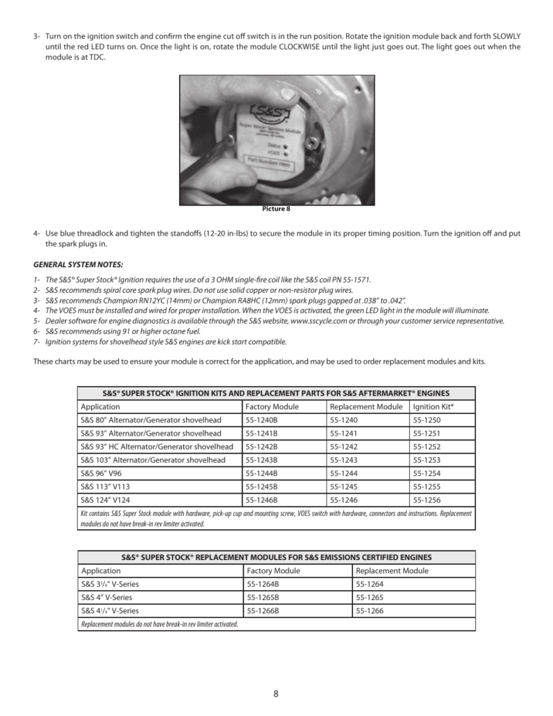
The coil’s low-tension side is to be connected to the chassis’ positive. This is what’s called the ground on the ignition wiring diagram. The high-tension component supplies the spark plugs with positive. To prevent noise, the coil’s body metal is required to be connected to the chassis. It is not required to use electricity. There are also connections between the negative and positive coil’s terminals on an diagram of the ignition wiring. It is possible to find an ignition coil problem which can be identified by scanning it in an auto parts store.
The black-and-white-striped wire from the harness goes to the negative terminal. The positive terminal also gets the second white wire, which is black in its trace. The contact breaker is linked to the black wire. To verify the wires’ connections, use a paperclip to lift them off the housing. Be sure that the terminals aren’t bent.
Accessory terminals
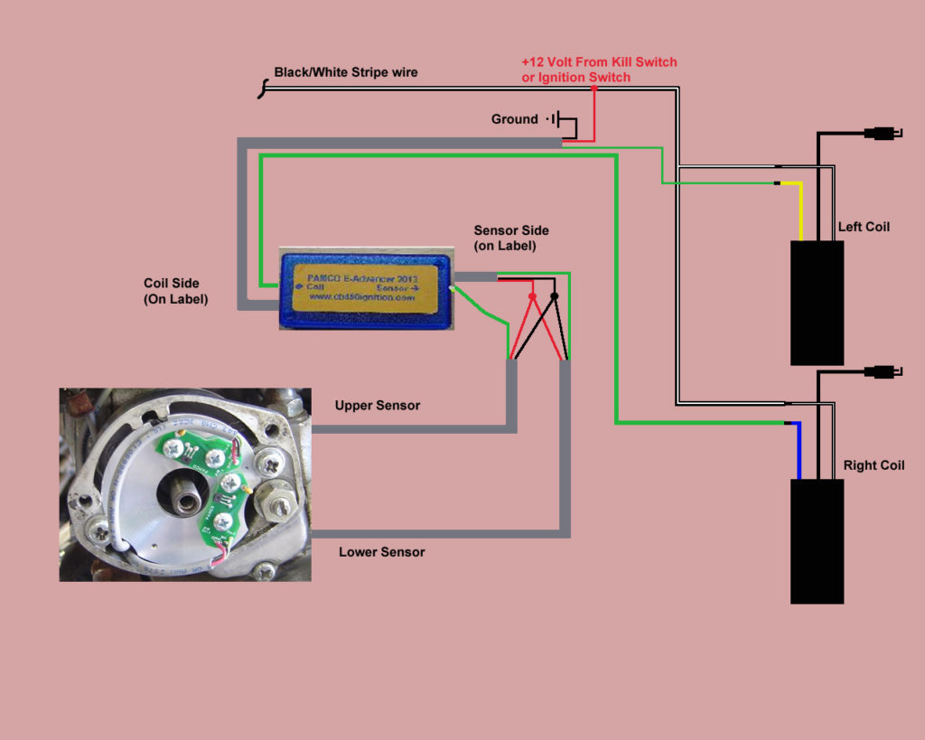
The wiring diagrams of the ignition illustrate the different wires used to power the various components of the car. There are typically four colors of terminals connected to each part. For accessories, red is for starter solenoid, yellow for battery, and blue is for accessory. The “IGN terminal” is used to run the wipers, along with other operational functions. The diagram illustrates how you can connect ACC or ST terminals, and other.
The terminal BAT holds the battery. The electrical system can’t be started without the battery. The switch won’t be able to turn on if there is no battery present. To locate your car’s battery look over your wiring diagram. The ignition switch is connected to the battery of your car. The BAT connector is connected to the battery.
Some ignition switches offer an additional “accessory position” that allows users to alter their outputs without the ignition. Some customers want the output of the auxiliary to be used separately from the ignition. To allow the auxiliary output to be used, connect the connector in the same shade as the ignition. Then , connect it to the ACC end of the switch. This is a useful feature, but there is an important difference. Most ignition switches will be in an ACC position if the car is in the ACC however they will be at the START position when the car is in IGN.
Gallery of S&s Ist Ignition Wiring Diagram
Gallery of S&s Ist Ignition Wiring Diagram


