Suzuki Ignition Switch Wiring Diagram – We will first look at the various types of terminals on the ignition switch. These are terminals for the Ignition, Coil, or Accessory. After we’ve identified the terminals that are utilized, we can begin to identify the different components of the Suzuki Ignition Switch Wiring Diagram. In addition, we will discuss the different functions of the Ignition Switch and the Coil. After that, we will concentrate on the accessory terminals.
Terminals of ignition switch
An ignition switch is made up of three switches. These are responsible for feeding the battery’s power to various locations. The first switch is utilized to drive the choke by pushing it, while the second is for the ON/OFF position. Different manufacturers have different color-coding systems to identify different conductors. This will be covered in another article. OMC uses this system. Connectors can be connected to the ignition switch to connect a digital Tachometer.
Although the majority of ignition switch terminals don’t carry an original number, they may have a different one. Check the integrity of the wires to determine if they’re plugged into the correct ignition switch. A multimeter is a great instrument to verify the continuity. After you’re sure that the wires are running in good harmony, you can attach the new connector. If you have an ignition switch supplied by the manufacturer the wiring loom may be distinct from the one that is you have in your car.
Before connecting the ACC outputs to the auxiliary outputs of your car, it is important to know the fundamentals of these connections. The ACC/IGN connections function as the default connection on the ignition switch. The START/IGN terminals connect to the radio or stereo. The ignition switch controls the car’s engine. The terminals of older vehicles ignition switches are identified with “ACC” and ST (for specific magneto wires).
Terminals for coil
Understanding the terminology is the first step to finding out what kind of ignition coil you have. In a basic ignition wiring diagram, you will see a number of different terminals and connections, including two primary and two secondary. Each coil comes with its own operating voltage. To determine which type of coil you have the first step is to determine the voltage at S1, the primary terminal. S1 must also go through resistance tests to determine if it are a Type A or B coil.
The coil’s low-tension component must be connected with the chassis positive. This is the wiring diagram you will see in the diagram of wiring. The high-tension side provides positive direct to the sparkplugs. To prevent noise, the coil’s metal body is required to be connected to the chassis. It is not necessary to connect the coil electrically. The wiring diagram of the ignition will explain how to connect the two terminals of the positive and negative coils. There could be an issue with the ignition coil that is easily identified by scanning it in an auto parts retailer.
The black-and-white-striped wire from the harness goes to the negative terminal. The terminal for the negative is served by the black trace that’s joined to the white wire. The black wire connects to the contactbreaker. To check the connection, use a paperclip or a pencil to lift them out from the plug housing. It is also important to make sure that the connections aren’t bent.
Accessory terminals
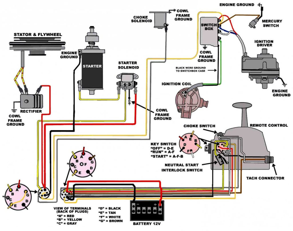
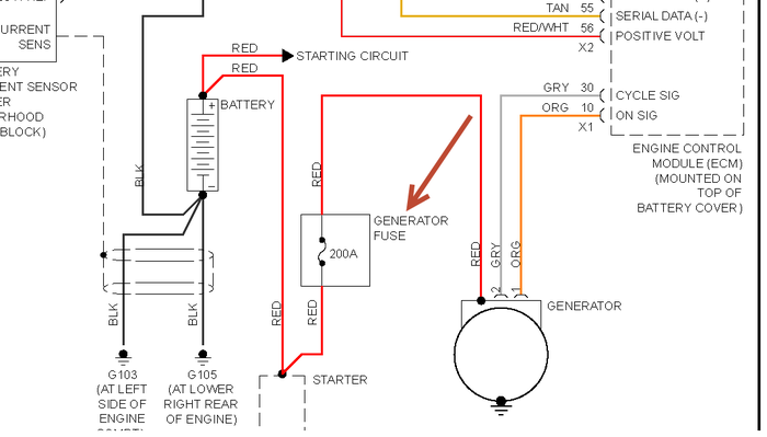
Diagrams of ignition wiring show the different wires that are used to power the car’s various components. There are usually four terminals with color codes that are connected to the component. To identify accessories, red is the starter solenoid’s color, yellow for battery and blue for accessory. The “IGN terminal” is used to provide power to the wipers as well as other operating features. The diagram illustrates how you can connect ACC or ST terminals and the rest.
The terminal referred to as BAT is where the battery is connected. The electrical system can’t begin without the battery. Also, the switch won’t start without the battery. To locate your car’s battery examine the wiring diagram. The accessory terminals of your car connect to the ignition switch as well as the battery. The BAT terminal is connected to the battery.
Certain ignition switches provide the option of an “accessory position” that lets users modify their outputs independent of the ignition. Users may wish to use the auxiliary output independently of the ignition. To use the auxiliary output, wire the connector using the same colors as ignition, and connect it to the ACC terminal on the switch. This convenience feature is great however, there’s one difference. The majority of ignition switches have an ACC position when the vehicle is in ACC however they’ll be at the START position when the vehicle is in IGN.
Gallery of Suzuki Ignition Switch Wiring Diagram
Gallery of Suzuki Ignition Switch Wiring Diagram


