Suzuki Ignition Wiring Diagram – In the beginning, we’ll take a look at the various kinds of terminals found on the ignition switch. They are the terminals used for Coil, Ignition Switch, and Accessory. Once we understand the function of each type of terminal, we are able to identify the various components of the ignition wiring. We will also discuss the function of the Ignition switch and Coil. Following that, we’ll shift our attention to the Accessory terminals.
Terminals for ignition switch
An ignition switch is composed of three different switches. They are responsible for feeding the battery’s power to various locations. The first switch supplies power to the choke whenever it is pushed. The second is the ignition switch’s ON/OFF position. Each manufacturer has their individual color-coding system that we’ll discuss in a subsequent article. OMC uses this method. Connectors can be connected to the ignition switch to include an electronic tachometer.
While the majority of ignition switch terminals don’t carry an original number, they might be equipped with a different number. Check the continuity of the wires to determine if they’re connected to the ignition switch correctly. A cheap multimeter can assist you in this. When you’re satisfied with the continuity of the wires, then you’ll be able to connect the new connector. If you are using an ignition switch that is supplied by the manufacturer the wiring loom may be different from that used in your vehicle.
It is important to understand the way that ACC outputs and auxiliary outputs work in order to join them. The ACC and IGN connectors are the standard connections of the ignition switch. The START, IGN, and ACC terminals are the main connections for radios or stereo, the START/IGN terminals are the primary ones. The ignition switch regulates the engine in your car. The ignition switch terminals on older cars are identified with the letters “ACC” as well as “ST” (for the individual magneto wires).
Terminals for coil
To determine the type of ignition coil, the initial step is to learn the terminology. A basic diagram of the wiring will reveal a variety of connections and terminals. The coils come with a distinct operating voltage. The initial step in determining which type you have will involve testing the voltage at S1, the main terminal. S1 must be tested for resistance in order to identify if the coil is type A, B and/or C.
The chassis’ negative must be connected to connect the coil’s low-tension side. This is also the ground in an ignition wiring diagram. The high tension side supplies positive directly the spark plugs. It is required for the purpose of suppression that the metallic body of the coil is connected to its chassis, however it isn’t essential. The wiring diagram for the ignition will show you how to connect the terminals of the negative or positive coils. Sometimes, a check at an auto parts shop can diagnose a malfunctioning ignition wire.
The black-and-white-striped wire from the harness goes to the negative terminal. The terminal for the negative is served by the trace in black that’s connected to the white wire. The black wire goes to the contact breaker. If you’re not certain about the connections between the twowires, use an old paper clip to take them from the plug housing. Make sure that the connectors aren’t bent.
Accessory terminals
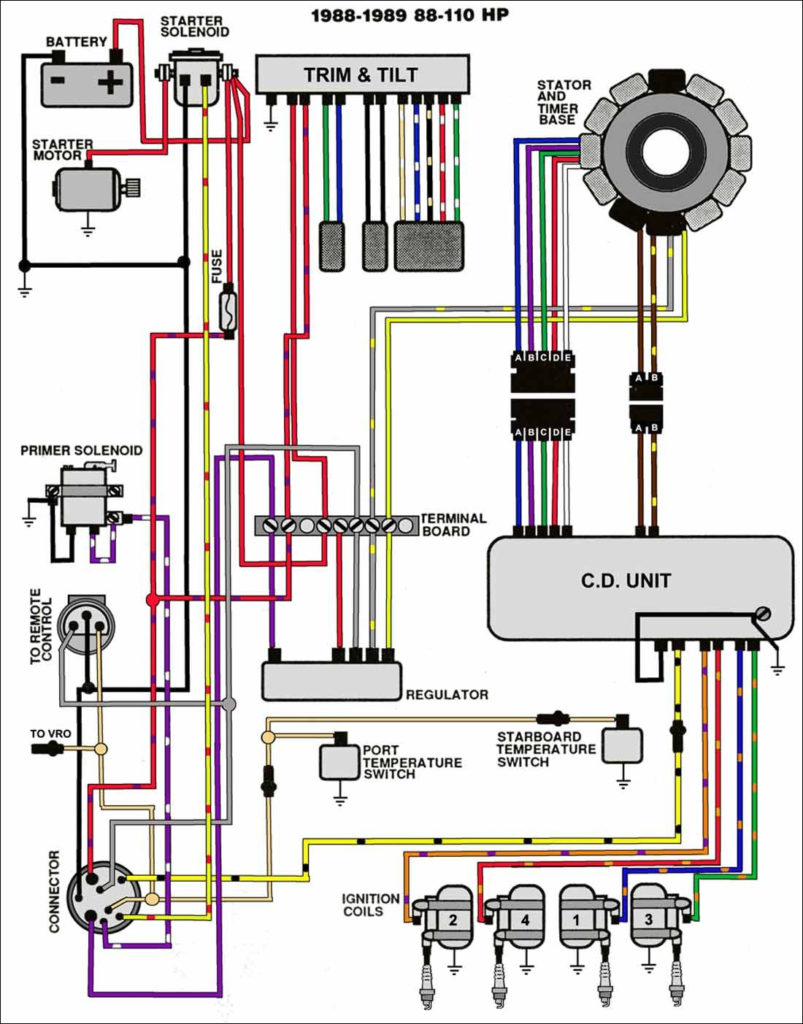
The diagrams for ignition wiring depict the wiring used to power the vehicle’s electrical supply. Each component has four distinct connections that are color coded. To identify accessories, red stands for starter solenoid, blue for battery, and blue is for accessories. The “IGN” terminal is used to start the vehicle and control the wipers, as well as other operating functions. The diagram shows how to connect ACC or ST terminals as well as the rest.
The terminal BAT is where the battery is. The electrical system is not able to start without the battery. Additionally, the switch will not start without the battery. The wiring diagram will inform you the location of your car’s battery. The accessory terminals in your vehicle are connected to the battery and the ignition switch. The BAT Terminal is connected to the Battery.
Some ignition switches come with an additional “accessory position” which allows users to alter their outputs without the ignition. Some customers might want to utilize the auxiliary input separately from the ignition. You can use the secondary output by connecting it to an ACC terminal on the switch that has the same color. This feature of convenience is fantastic however, there’s one difference. Most ignition switches are set to operate in the ACC position when the vehicle is in the ACC position, whereas they’re set to the START position when the car is in the IGN position.
Gallery of Suzuki Ignition Wiring Diagram
Gallery of Suzuki Ignition Wiring Diagram


