Suzuki Samurai Ignition Switch Wiring Diagram – We will first look at the various types and purposes of the terminals found in the ignition switches. These terminals serve for the Ignition button, Coil and Accessory. Once we have identified what these terminals do then we can determine the various components in the ignition wiring. In addition, we will discuss the different functions of the Ignition Switch and the Coil. We will then discuss the roles of the Ignition switch as well as Coil.
Terminals of ignition switch

Three switches are found on the ignition switch. Each of the three switches is able to feed the battery’s voltage to various locations. The first switch supplies power to the choke when it is pushed. The second is the switch that controls the ignition’s ON/OFF positions. Different manufacturers employ various color codes for the different conductors. This is discussed in a separate article. OMC follows this procedure. The connector permits the attachment of a speedometer to the ignition switch.
Although the majority of ignition switch terminals don’t carry an original number, they may have a different one. To make sure that your wires are correctly connected to the switch, you must verify their continuity. A simple multimeter will aid in this. After you’ve confirmed the continuity of the wires you can then connect the connector. The wiring loom in the ignition system switch supplied by the manufacturer differs.
In order to connect the ACC outputs to the auxiliary outputs on your car, you’ll need to first understand how these two connections work. The ACC, IGN and START terminals are your default connection to the ignition switch. They also function as the primary connections to your radio and stereo. The ignition switch controls the car’s engine. Older cars have the ignition switch’s terminals that are labeled “ACC” or “ST” (for individual magnetowires).
Terminals for coil
To determine the type of ignition coil, the first step is to understand the terminology. The basic ignition wiring diagram depicts various connections and terminals. There are two primary and one secondary. The coils are equipped with a particular operating voltage, and the first step to determine which one you have will involve testing the voltage of S1 the main terminal. S1 must be tested for resistance in order to identify if the coil is type A, B or C.
The negative of the chassis must be connected to the low-tension side. It is also the ground on an ignition wiring diagram. The high-tension side supplies positive directly to the spark plugs. To prevent noise the coil’s metal body is required to be connected to the chassis. It’s not necessary for electrical use. The wiring diagram will also illustrate the connection between the positive and negative coils. Sometimes, an inspection at an auto part store can diagnose a malfunctioning ignition wire.
The black-and-white-striped wire from the harness goes to the negative terminal. The other white wire is black and connects to the terminal opposite. The black wire connects to the contact breaker. It is possible to remove the black wire from the plug housing using a paper clip in case you are uncertain about the connections. Be sure to check that the terminals have not been bent.
Accessory terminals
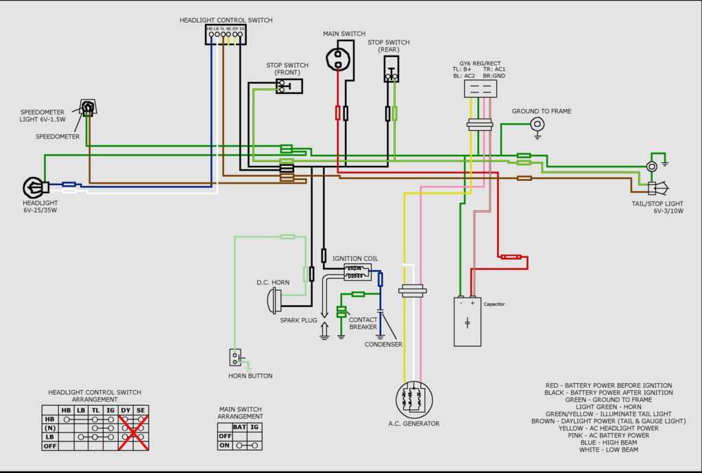
Diagrams of ignition wiring show the different wires that are utilized to power the vehicle’s various parts. There are generally four colored terminals that correspond to the component. The accessories are red while the battery is yellow, the starter solenoid is green. The “IGN terminal” is used to provide power to the wipers along with other operational functions. This diagram shows how you can connect ACC and ST terminals with the rest of components.
The terminal BAT connects the battery to the charger. The electrical system won’t start if the battery isn’t connected. The switch won’t turn off if the battery isn’t present. A wiring diagram can inform you where to find the battery of your car. The ignition switch as well as the battery are connected via accessory terminals. The BAT terminal is connected to the battery.
Certain ignition switches have an accessory position. It allows users to access their outputs from another location without the ignition. Some customers prefer to make use of an additional output independent of the ignition. To make use of the auxiliary output, wire the connector using the same colors as ignition, and connect it to the ACC terminal on the switch. Although this is a great feature, there’s one thing you need to know. Most ignition switches will be in an ACC position if the car is in ACC however, they will be at the START position when the vehicle is in IGN.
Gallery of Suzuki Samurai Ignition Switch Wiring Diagram
Gallery of Suzuki Samurai Ignition Switch Wiring Diagram


