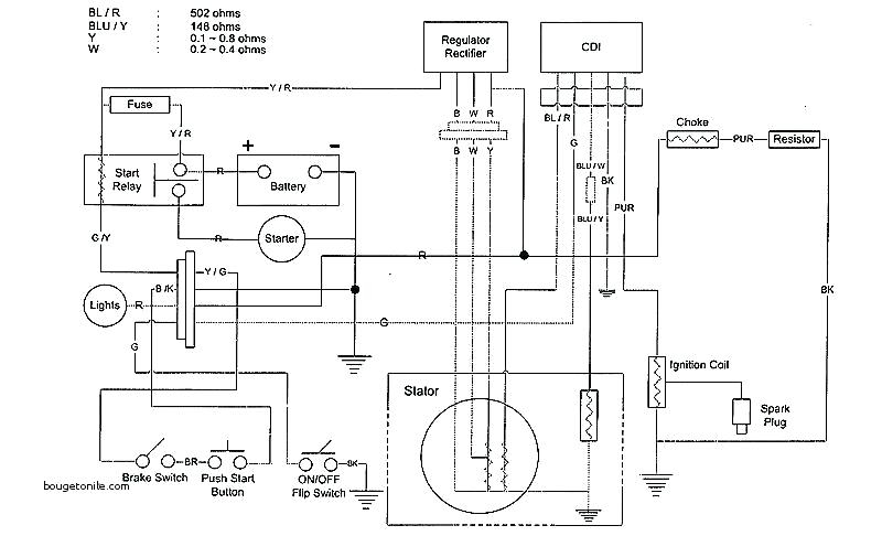
Taotao 50 Ignition Wiring Diagram – First, we will examine the various types of terminals found in the ignition switch. These include the terminals that are for the Ignition switch, Coil, and Accessory. Once we know the purpose of these terminals are used for then we can identify the different parts of the Taotao 50 Ignition Wiring Diagram. In addition, we will discuss the roles of the Ignition switch, and Coil. Following that, we will move on to the Accessory Terminals.
Terminals for ignition switches
An ignition switch is composed of three switches. They are responsible for feeding the battery’s power to various locations. The ON/OFF position of the ignition switch is controlled by the third switch, which delivers power to the choke whenever it’s pushed. Different manufacturers have different color-coding systems to identify different conductors. This will be covered in another article. OMC utilizes the same system. An additional connector is included inside the ignition switch for connecting an to a tachometer.
Although the majority of ignition switch terminals don’t have an original number, they might be equipped with a different number. Before you plug into the ignition switch, be sure to test the continuity. A cheap multimeter can help you do this. After you’re sure that all wires are in good order then you can connect the new connector. If your vehicle has an original ignition switch supplied by the factory (or a wiring loom) the wiring loom may differ from that of your car.
It is important to understand the ways in which the ACC outputs and the auxiliary outputs function in order to join them. The ACC/IGN terminals function as the default connections for the ignition switch. The START/IGN terminals are connected to the stereo or radio. The ignition switch is accountable to turn the car’s engines on and off. The ignition switch terminals on older cars are identified with the initials “ACC” and “ST” (for each magneto wires).
Terminals for coil
To identify the kind of ignition coil you need to know the step is to understand the terminology. The diagram of the basic ignition wiring illustrates a variety of connections and terminals. There are two primary and one secondary. Each coil operates at a specific voltage. The first step to determine which kind you’re using is to examine the voltage of S1 or the primary terminal. S1 should be checked for resistance to determine if the coil belongs to Type A, B, and/or C.
The chassis’ negative must be connected to the side of low-tension. This is what is known as the ground for the wiring for ignition. The high-tension side provides positive direct to the sparkplugs. It is necessary for suppression purposes that the body of the coil’s metal be connected to its chassis but not essential. The wiring diagram of the ignition will demonstrate how to connect the two terminals of the positive and negative coils. You may find an ignition coil problem that can be easily diagnosed by scanning it at an auto parts store.
The black-and-white-striped wire from the harness goes to the negative terminal. Positive terminal gets the second white wire, which has a black trace. The black wire goes to the contact breaker. To verify the wires’ connections use a paperclip to remove them out of the housing. Make sure you don’t bend the connectors.
Accessory terminals
Diagrams of ignition wiring show the different wires that are used to power the car’s various components. There are generally four colored terminus lines for each component. For accessories, red is the starter solenoid’s color, yellow is for battery, and blue is for accessory. The “IGN” terminal is used to start the vehicle, controlling the wipers and other functions. The diagram demonstrates how to connect the ACC and ST terminals to the rest of the components.
The terminal BAT is the connector for the battery. The electrical system won’t start without the battery. In addition, the switch will not start. You can refer to your wiring diagram if you’re unsure where your car’s batteries are located. The accessory terminals of your car connect to the ignition switch and the battery. The BAT connector connects to your battery.
Some ignition switches have the “accessory” position that permits users to control their outputs , without needing to utilize the ignition. Sometimes, a customer wants to make use of the auxiliary output separately from the ignition. In order for the auxiliary output be used, wire the connector with the same shade as the ignition. Then connect it with the ACC end of the switch. This option is useful, but it has one major distinction. The majority of ignition switches have an ACC position if the car is in the ACC, but they’ll be in the START position when the vehicle is in IGN.
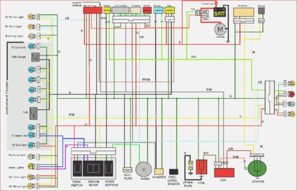
Gallery of Taotao 50 Ignition Wiring Diagram
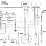
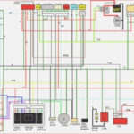
Gallery of Taotao 50 Ignition Wiring Diagram


