Tohatsu Ignition Switch Wiring Diagram – Let’s start by looking at the different types of terminals on the ignition switch. They include terminals for the Ignition switch, Coil, and Accessory. After we’ve identified the terminals that are utilized, we can begin to identify the different components of the Tohatsu Ignition Switch Wiring Diagram. We’ll also be discussing the function of the Ignition switch and Coil. Following that, we will move on to the Accessory Terminals.
Terminals for ignition switch
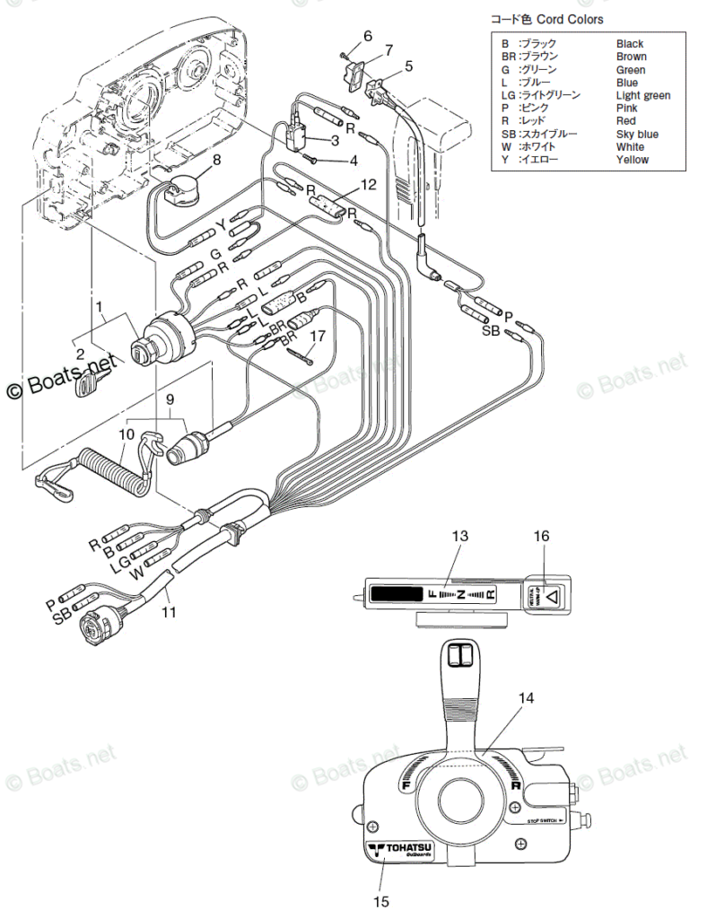
There are three separate switches on the ignition switch, and they transmit the battery’s current voltage to several different locations. The first switch provides power to the choke, while the second switch controls the ON/OFF state of the switch. Different manufacturers have different color-coding systems for different conductors. We’ll discuss this in another article. OMC uses this system. The adapter is attached to the ignition switch to allow for the addition of a tonometer.
Even though many ignition switch terminals do not come in original form, the numbering may not be in line with the diagram. You should first check the continuity of the wires to determine if they’re plugged into the ignition switch in the correct way. This can be checked using an inexpensive multimeter. After you have verified the integrity of the wires you can then install the connector. The wiring loom for an ignition switch that’s supplied by the manufacturer will differ from the one you have in your car.
Understanding how the ACC outputs are connected to the other outputs inside your car is vital. The ACC and IGN connectors are the standard connections for your ignition switch. While the START, IGN, and ACC terminals are primary connections for radios or stereo, the START/IGN connections are the primary ones. The ignition switch controls the car’s engine. Older cars have the ignition switch terminals labeled “ACC” or “ST” (for individual magnetowires).
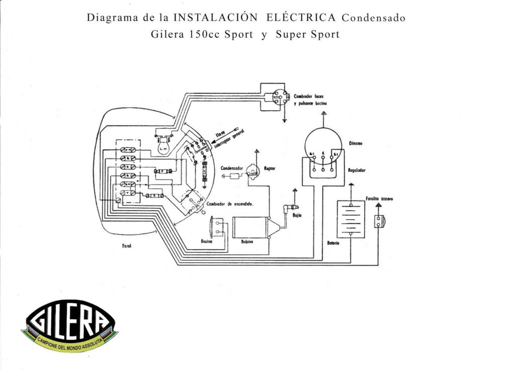
Terminals for coil
To determine the type of ignition coil, the initial step is to understand the terms. The diagram of the basic ignition wiring depicts various connections and terminals. There are two primary and one secondary. Each coil operates at a specific voltage. The first step in determining which kind of coil you’re dealing with is to test the voltage at S1 or the primary terminal. S1 must also go through resistance testing to determine if it is a Type A or B coil.
The low-tension coil side must be connected at the chassis’s plus. This is what is known as the ground for the wiring for ignition. The high-tension supply delivers positive directly to spark plugs. To reduce the noise the body of the coil must be connected to chassis. It is not necessary to electrically connect. The wiring diagram for ignition will also outline the connections of the positive coil terminals. Sometimes, a check at an auto part store can diagnose a malfunctioning ignition wire.
The black-and-white-striped wire from the harness goes to the negative terminal. The white wire also is black with a trace, and it goes to the positive terminal. The black wire is connected to the contact breaker. If you’re not sure about the connection between both, you can use the clip of a paperclip to remove them from the plug housing. Be sure that the terminals aren’t bent.
Accessory terminals
Diagrams of the ignition wiring illustrate the wires that supply power to different parts of the car. Each part has four distinct connections that are color coded. Red stands for accessories, yellow represents the battery and green is for the starter solenoid. The “IGN” terminal is used to start the car , and also to operate the wipers and other operating features. The diagram shows how you can connect the ACC and ST terminals to the rest of the components.
The terminal BAT connects the battery to the charger. Without the battery the electrical system will not start. Furthermore the switch won’t come on. To find the battery in your car look over your wiring diagram. The ignition switch and the battery are connected through the accessory terminals. The BAT connector connects to your battery.
Some ignition switches offer an additional “accessory position” that lets users adjust their outputs independently of the ignition. Users may wish to use the auxiliary output independently of the ignition. To use the additional output, wire the connector in identical colors to the ignition and connect it to the ACC terminal on the switch. This convenience feature is great however there’s a difference. The majority of ignition switches are set up to show an ACC status when the car’s in either the ACC or START position.
Gallery of Tohatsu Ignition Switch Wiring Diagram
Gallery of Tohatsu Ignition Switch Wiring Diagram


