Total Loss Ignition Wiring Diagram – Let’s first examine the different kinds and functions of terminals on the ignition switches. These terminals are used for the Ignition button, Coil and Accessory. When we have a clear understanding of the purpose of each terminal, we are able to identify the various components of the ignition wiring. We will also discuss the roles of the Ignition switch and the Coil. Then, we’ll focus to the accessory terminals.
Terminals for ignition switches
An ignition switch contains three separate switches that feed the battery’s current to different destinations. The first switch supplies power to the choke whenever it is pushed. The third is the switch that controls the ignition’s ON/OFF positions. Different manufacturers have distinct color-coding systems that correspond to the conductors. OMC uses this approach. Connectors can be attached to the ignition switch in order to include a digital tachometer.
Even though most ignition switch terminals do not have an initial number, they could have a different number. Before you plug into the ignition switch be sure to test the continuity. This can be done using an inexpensive multimeter. After you’re satisfied with the connection it’s time to connect the new connector. If you’re using a factory-supplied ignition switch the wiring loom will be distinct from the one that is in your car.
Knowing how the ACC outputs are connected to the auxiliary outputs inside your vehicle is crucial. The ACC/IGN connections function as the default connections on the ignition switch. The START/IGN terminals connect to the stereo or radio. The ignition switch is responsible for turning the engine of your car to and off. Older vehicles have ignition switch terminals labeled “ACC” or “ST” (for individual magnetowires).
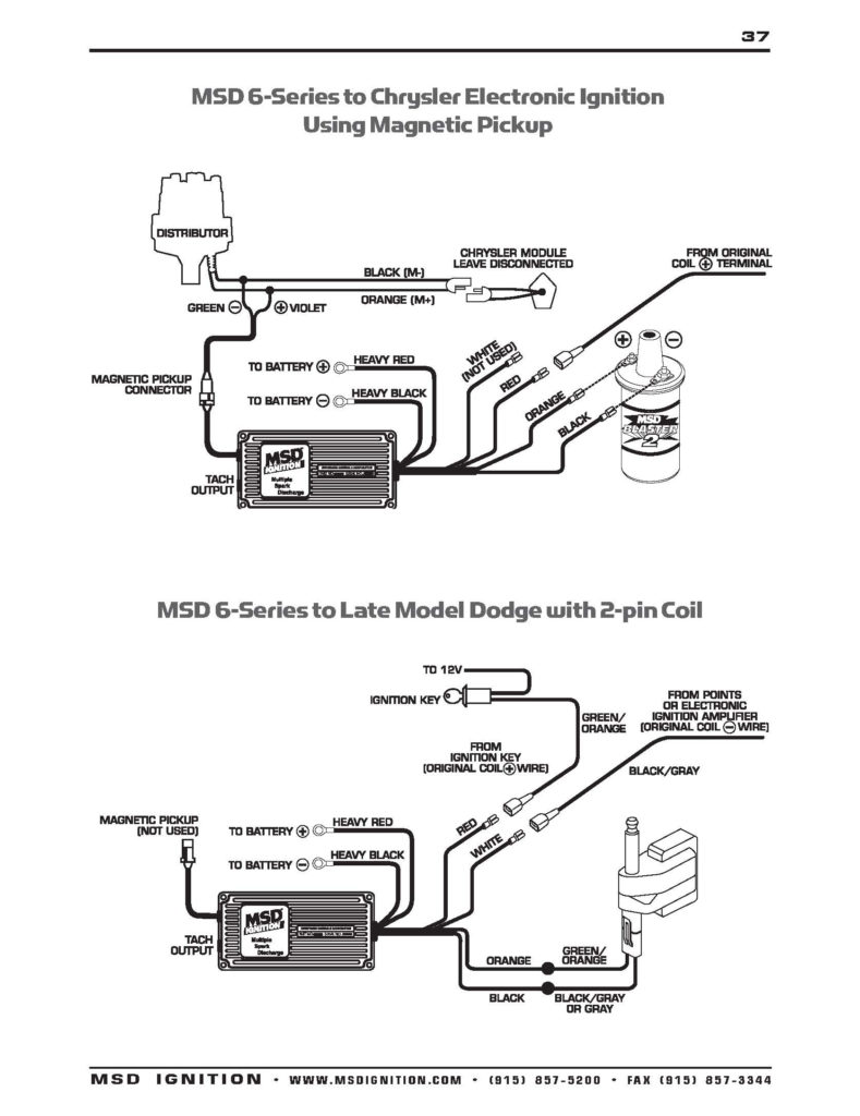
Terminals for coil
The terms used to define the model and type of the ignition coil is the most important thing. An understanding of the basic wiring diagram for ignition will show you a number of connections and terminals. Each coil is equipped with a distinct operating voltage. To determine which type of coil you have the first step is to check the voltage at the S1 primary terminal. You should also examine S1 for resistance in order to determine if it’s an A or B coil.
The chassis’ negative should be connected to the coil’s low-tension side. This is the ground of the ignition wiring. The high tension part supplies positive power directly to the spark plugs. It is required for the purpose of suppression that the coil’s metallic body be connected to its chassis however it isn’t essential. The diagram of the ignition wiring will also show the connection of the positive coil terminals. It is possible to find an issue with your ignition coil which can be identified by scanning it at an auto parts store.
The black-and-white-striped wire from the harness goes to the negative terminal. The other white wire has a black color and connects to the terminal opposite. The contact breaker is connected to the black wire. To test the wires’ connections, employ a paperclip to remove them out of the housing. You should also check to ensure that the terminals are not bent.
Accessory terminals
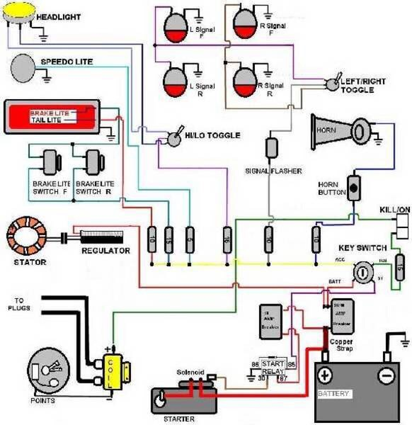
Diagrams of ignition wiring show the different wires used for powering the various components. Each component has four distinct colored connections. The red color represents accessories, yellow represents the battery and green for the solenoid for starters. The “IGN” terminal is used to start the car, turn on the wipers, and other features. This diagram demonstrates how to connect ACC and ST terminals with the rest of the components.
The terminal BAT connects the battery to the charger. The battery is essential to allow the electrical system to get started. The switch will not turn on if the battery isn’t there. You can refer to your wiring diagram if you’re unsure where your car’s batteries are located. The ignition switch as well as the battery are connected through the accessory terminals. The BAT connector connects to your battery.
Some ignition switches feature an additional “accessory” position, in which users can manage their outputs without using the ignition. Some customers may prefer to utilize the auxiliary output separately from the ignition. It is possible to use the auxiliary input by connecting it to the ACC terminal. This is a convenient feature however it does have one major differentiator. Many ignition switches have an ACC position when your vehicle is in the ACC mode, and a START position when the switch is in IGN.
Gallery of Total Loss Ignition Wiring Diagram
Gallery of Total Loss Ignition Wiring Diagram


