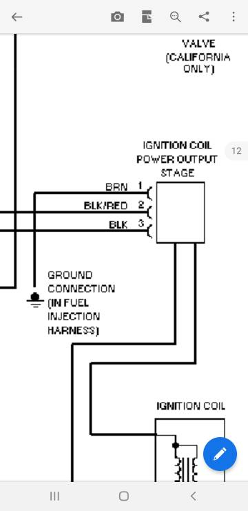
Tp100 Ignition Module Wiring Diagram – The first step is to look at the different terminals used on the ignition switch. These include the terminals for the Ignition switch, Coil, and Accessory. Once we have established the purpose of these terminals are, we will proceed to determine the various parts of the Tp100 Ignition Module Wiring Diagram. We’ll also discuss the functions of the Ignition switch, and Coil. Then, we will focus on the accessory terminals.
Terminals for ignition switches
There are three switches in the ignition switch, and they provide the battery’s voltage to a variety of destinations. The first switch provides power to the choke, while the second toggles the on/off status of the ignition switch. Different manufacturers have different colors-coding systems to match the conductors. OMC utilizes this method. The adapter is attached to the ignition switch that allows the addition of an tonometer.
Although the majority of ignition switch terminals don’t come in original form The numbering might not be in line with the diagram. Examine the electrical continuity first to ensure that they’re connected correctly to the ignition switch. This can be checked using a simple multimeter. Once you are satisfied that the wires are in good order, you can attach the new connector. The wiring loom used for an ignition switch that is factory-supplied will be different than the one you have in your car.
Before you can connect the ACC outputs to your car’s auxiliary outputs it is crucial to understand the basics of these connections. The ACC and IGN terminals are the default connection on your ignition switch. the START and IGN terminals are the principal connections for the stereo and radio. The ignition switch is responsible for turning the engine of your car on and off. The terminals for the ignition switch on older vehicles are marked with the alphabets “ACC” as well as “ST” (for each magneto wires).
Terminals for coil
Understanding the terms is the first step to determining which type of ignition coil you have. The basic ignition wiring diagram shows a number different connections and terminals. There are two primary and secondary connections. The voltage that operates on every coil is different. Therefore, it is important to first test the voltage at the S1 (primary terminal). S1 should be tested for resistance in order to identify if the coil is Type A, B, or C.
The low-tension coil side must be connected to the chassis’s minus. This is what you see in the diagram of wiring. The high tension side provides positive power directly to the spark plugs. For suppression purposes, the coil’s metal body is required to be connected to the chassis. However, it is not necessary to electrically connect. The wiring diagram of the ignition will show you how to connect the terminals of either the positive or negative coils. In some cases, you’ll find that an ignition coil that is malfunctioning is easily identified with scanning in an auto parts store.
The black-and-white-striped wire from the harness goes to the negative terminal. The positive terminal also receives a white wire that is black in its trace. The black wire connects with the contact breaker. To check the wires’ connections, employ a paperclip to lift them out of the housing. It is also important to make sure the terminals aren’t bent.
Accessory terminals
The diagrams for ignition wiring illustrate the wires that are used in the power supply of the vehicle. Typically, there are four different color-coded terminals for each component. For accessories, red is for starter solenoid, yellow is for battery, and blue is for accessories. The “IGN” terminal is used for starting the car, operating the wipers and various other functions. The diagram shows how to connect the ACC and ST terminals to the other components.
The battery is attached to the terminal whose name is BAT. The battery is vital to allow the electrical system to get started. The switch won’t be able to turn off if the battery isn’t present. To locate your car’s battery look over your wiring diagram. The ignition switch is linked to the car’s battery. The BAT terminal is connected to the battery.
Certain ignition switches come with an “accessory” setting that permits users to control their outputs without needing to utilize the ignition. Sometimes, customers want to make use of the auxiliary output separate from the ignition. The auxiliary output could be connected by wiring the connector with the same colors as the ignition, and then attaching it to the ACC terminal of the switch. This convenience feature is great however, there’s one differentiator. The majority of ignition switches have an ACC position if the car is in ACC however they’ll be in the START position if the vehicle is IGN.
Gallery of Tp100 Ignition Module Wiring Diagram
Gallery of Tp100 Ignition Module Wiring Diagram


