Ultima Digital Ignition System Wiring Diagram – Let’s begin by looking at different types of terminals in an ignition switch. These include the terminals that are for the Ignition switch, Coil, and Accessory. Once we know the purpose of these terminals are used for We will then discover the various components of the Ultima Digital Ignition System Wiring Diagram. We will also talk about the functions as well as the Coil. After that, we’ll turn our attention to the Accessory terminals.
Terminals for ignition switches
Three switches can be found in an ignition switch. Each of these switches transmits the battery’s current to various locations. The first switch powers the choke. The third switch regulates the ON/OFF of the ignition switch. Every manufacturer has its individual color-coding system that we’ll discuss in a subsequent article. OMC follows this scheme. The connector permits the attachment of a speedometer to the ignition switch.
Even though some ignition switch terminals do not come in original form however, the numbers may not be in line with the diagram. Before plugging into the ignition switch, ensure that you check the continuity. This can be accomplished using a cheap multimeter. After you’re satisfied with the continuity then you can connect the new connector. The wiring loom for an ignition switch that’s factory-supplied will be different than the one you have in your car.
First, understand the differences between the ACC and secondary outputs. The ACC and IGN connectors are the default connections of your ignition switch. Although the START, IGN, and ACC terminals are the main connections for radios or stereo, the START/IGN terminals are the most important ones. The ignition switch is the one that controls the engine of your car. The terminals of older cars’ ignition switches are labeled by “ACC” and ST (for individual magneto wires).
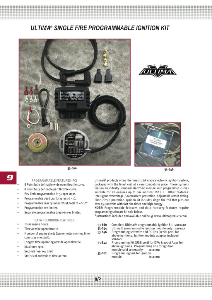
Terminals for coil
The terminology used to determine the model and type of the ignition coil is the first thing. The basic ignition wiring diagram shows a number different connections and terminals. There are two primary and secondary connections. You must determine the type of coil you own by examining the voltage on the primary terminal S1. S1 should be tested for resistance in order to determine if the coil is Type A, B, or C.
The lower-tension side of the coil needs to be connected to the chassis’ negative. This is also the ground in the diagram of ignition wiring. The high tension side provides positive power directly to the spark plugs. The body of the coil has to connect to the chassis for suppression purposes, but it is not electrically essential. The wiring diagram will illustrate the connection between the positive and negative coil terminals. Sometimes, a check at an auto parts shop can identify a problem with the ignition wire.
The black-and-white-striped wire from the harness goes to the negative terminal. The positive terminal is connected to the white wire, which has a black trace. The contact breaker is attached to the black wire. To confirm the connections, you can employ a paperclip, or a pencil to pull them out from the plug housing. It’s also crucial to make sure that the terminals don’t bend.
Accessory terminals
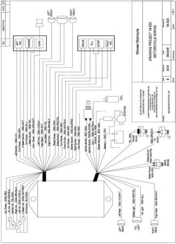
Diagrams of the ignition wiring depict the wiring used to power various parts of the car. There are generally four color-coded terminals that correspond to the respective component. Red is used to indicate accessories, yellow is the battery and green for the starter solenoid. The “IGN” terminal allows you to start the car, control the wipers, and any other operation features. The diagram shows how you can connect the ACC and ST terminals to the other components.
The terminal BAT is the connection for the battery. The electrical system can’t begin without the battery. Additionally, the switch will not be able to turn on without the battery. If you’re not sure of where your car’s battery is situated, you can look at your wiring diagram to see where it is. The accessory terminals in your car are connected to the battery as well as the ignition button. The BAT Terminal is connected to the Battery.
Certain ignition switches provide an additional “accessory position” which allows users to alter their outputs without the ignition. Sometimes, customers want to use an auxiliary output that is not connected to the ignition. To use the auxiliary output, wire the connector using the same colors as the ignition connecting it to the ACC terminal on the switch. Although this is a great option, there’s a thing to be aware of. The majority of ignition switches are set up to display an ACC status when the car’s at either the ACC or START position.
Gallery of Ultima Digital Ignition System Wiring Diagram
Gallery of Ultima Digital Ignition System Wiring Diagram


