Universal Ignition Switch Wiring Diagram – Let’s begin by looking at different types terminals found in an ignition switch. These are the terminals that connect the Ignition, Coil, or Accessory. Once we’ve determined the function of the terminals we will be able to determine the various components of the ignition wiring. In addition, we will discuss the functions of both the Ignition Switch and the Coil. Following that, we will move on to the Accessory Terminals.
Terminals for ignition switch
Three switches are located on an ignition switch. Each of the three switches is able to feed the battery’s voltage to a variety of destinations. The first switch powers the choke. The second switch controls the ON/OFF function of the ignition switch. Different manufacturers utilize their own color-coding method for different conductors that is described in a separate article. OMC uses this method. The connector permits the attachment of a speedometer the ignition switch.
While the majority of ignition switch terminals do not have an initial number, they could have a different one. First, check the continuity of all wires to ensure they are correctly plugged into the ignition switches. A cheap multimeter can help you do this. When you’re happy with the continuity it’s time to connect the new connector. If your vehicle is equipped with an ignition switch that is installed the wiring diagram will differ.
The first step is to understand the distinctions between ACC and auxiliary outputs. The ACC and IGN connectors are the standard connections of your ignition switch. Although the START, IGN, and ACC terminals are primary connections to the radio or stereo, the START/IGN terminals are the main ones. The ignition switch switches the car’s engine ON and off. In older vehicles, the ignition switch terminals are marked with the letters “ACC” and “ST” (for distinct magnet wires).
Terminals for coil
To identify the kind of ignition coil, the first step is to learn the terminology. A simple diagram of the wiring will show a variety of terminals and connections comprising two primary and two secondaries. The operating voltage of each coil differs. Therefore, it is important to first test the voltage at the S1 (primary terminal). S1 should also be checked for resistance to determine if it’s a Type B, B, or an A coil.
The low-tension end of the coil should be connected to the chassis’ negative. This is the ground of the wiring for ignition. The high tension part supplies positive power directly to the spark plugs. It is essential for suppression purposes that the coil’s metallic body be connected to its chassis, however it isn’t essential. The wiring diagram of the ignition will explain how to connect the two terminals of the positive and negative coils. It is possible to find an issue with the ignition coil that is easily identified by looking it up at the auto parts shop.
The black-and-white-striped wire from the harness goes to the negative terminal. The white wire has a black color and connects to the negative terminal. The black wire connects with the contact breaker. You can examine the connections using a paperclip to take the wires out of the housing. Make sure you verify that the connections aren’t bent.
Accessory terminals
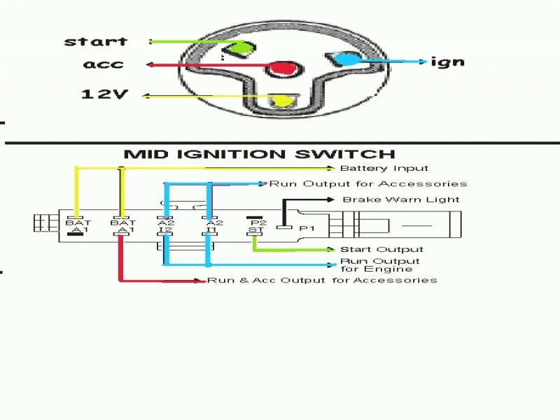
Ignition wiring diagrams depict the various wires that are used to power different components. There are typically four color-coded terminals to each component. Red is used to indicate accessories, yellow is the battery and green is the starter solenoid. The “IGN” terminal is used to start the car, operate the wipers, as well as other features. The diagram illustrates how to connect ACC or ST terminals as well as the rest.
The terminal BAT connects the battery to the charger. The electrical system won’t start when the battery isn’t connected. The switch won’t turn on if there is no battery present. It is possible to view your wiring diagram to figure out the location of your car’s batteries. placed. Your car’s accessory terminals connect to the ignition switch and the battery. The BAT terminal is connected to the battery.
Some ignition switches are equipped with an accessory position. This allows users to access their outputs from a different place without having to turn on the ignition. Sometimes, users want to use an auxiliary output independent of the ignition. The auxiliary output is used by wiring the connector with the same colors as the ignition, and then connecting it to the ACC terminal of the switch. This is an excellent option, but there’s an important distinction. Some ignition switches are programmed to have an ACC position when the vehicle is in the ACC position. They also will be in the START position when the vehicle has entered the IGN position.
Gallery of Universal Ignition Switch Wiring Diagram
Gallery of Universal Ignition Switch Wiring Diagram


