Volvo Penta Ignition Wiring Diagram – The first step is to take a look at the different kinds of terminals for the ignition switch. The terminals are the Ignition switch and Coil along with the Accessory. After we’ve identified the purpose of these terminals, it is possible to recognize the various parts of the ignition wiring. We will also talk about the functions and the Coil. Then, we will concentrate on the accessories terminals.
Terminals for ignition switch
There are three switches in an ignition switch, which transmit the battery’s current voltage to various destinations. The first one is utilized to drive the choke through pushing it, and the second is for the ON/OFF position. Different manufacturers have different color-coding schemes to identify different conductors. We’ll discuss this in a different article. OMC follows this approach. There is a connector in the ignition switch for attaching the tachometer.
Although the majority of ignition switch terminals can be duplicated, the numbers might not be in line with the diagram. First, check the continuity of each wire to make sure they’re properly connected to the ignition switches. This can be done using an inexpensive multimeter. Once you’ve verified the integrity of the wires you can then connect the connector. If your car has an ignition switch installed the wiring diagram may differ.
To connect the ACC outputs to the auxiliary outputs on your vehicle, you have to understand the way these two connections function. The ACC, IGN and START terminals are the primary connections to the ignition switch. They are also the main connections to the radio and stereo. The ignition switch is the one that controls the engine of your car. Older cars are identified by the letters “ACC”, “ST”, (for individual magneto cables) on their ignition switch’s terminals.
Terminals for coil
The first step to determine the type of ignition coil is to comprehend the terms that is used. In a basic ignition wiring diagram there are several different terminals and connections, including two primary and two secondary. The coils come with a distinct operating voltage. The initial step to determine which one you have will involve testing the voltage at S1, the main terminal. S1 must also be inspected for resistance to determine if it’s a Type B, B, or an A coil.
The chassis’ negative end should be connected to to the coil’s lower-tension end. It is also the ground in an ignition wiring diagram. The high-tension supply provides the spark plugs with positive electricity directly. The metal body of the coil needs to connect to the chassis for suppression purposes but is not electrically required. The wiring diagram of the ignition will demonstrate how to connect the terminals of the positive or negative coils. In some instances you’ll discover that the ignition coil is damaged and is identified by scans at an auto parts shop.
The black-and-white-striped wire from the harness goes to the negative terminal. The positive terminal also gets the white wire that is black in its trace. The black wire is connected to the contact breaker. You can take the black wire from the housing of the plug by using a paperclip If you’re unsure of the connection. Be sure to verify that the connections aren’t bent.
Accessory Terminals
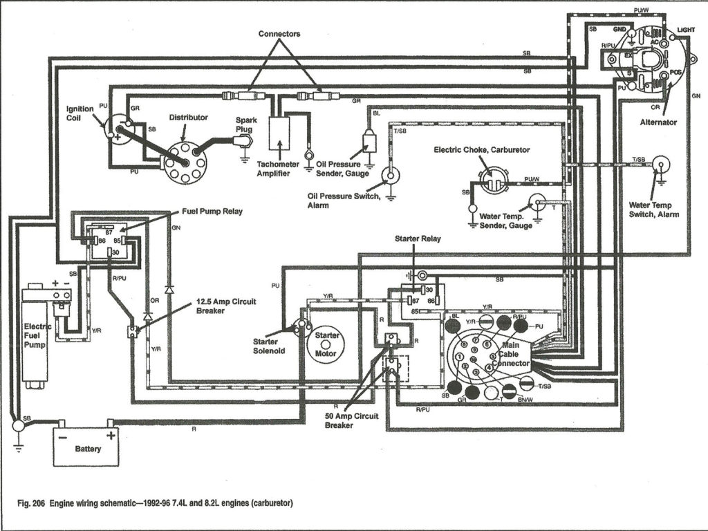
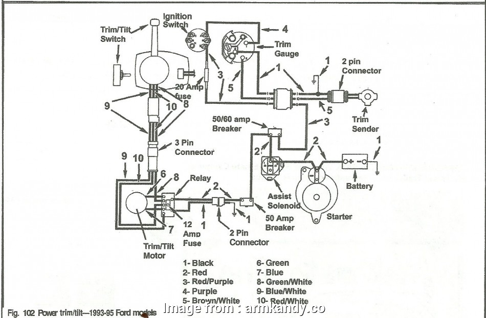
Diagrams of ignition wiring show the various wires utilized for powering the various components. There are typically four colored terminals for each component. For accessories, red is for starter solenoid, blue for battery, and blue for accessories. The “IGN terminal” is used to power the wipers as well as other operating features. This diagram shows how you can connect ACC and ST terminals to the rest of the components.
The terminal BAT is the connection to the battery. Without the battery the electrical system will not begin. A dead battery could make the switch stop turning on. To locate your car’s battery examine the wiring diagram. The ignition switch as well as the battery are connected by the accessory terminals. The BAT terminal is connected to the battery.
Some ignition switches are equipped with an accessory position. This lets users connect their outputs to a different place without the ignition. Sometimes, customers want to utilize an auxiliary output that is separate from the ignition. In order for the auxiliary output be used, plug in the connector with the same shade as that of the ignition. Then , connect it to the ACC end of the switch. This convenience feature is great however there’s a difference. A lot of ignition switches can be programmed to have an ACC position once the car is in the ACC position. They will also be in START mode when the vehicle has entered the IGN position.
Gallery of Volvo Penta Ignition Wiring Diagram
Gallery of Volvo Penta Ignition Wiring Diagram


