Vw Electronic Ignition Wiring Diagram – Let’s first look at the different terminals used on the ignition switch. These are terminals for the Ignition, Coil, or Accessory. Once we have established the purpose of these terminals are We will then discover the various components of the Vw Electronic Ignition Wiring Diagram. We will also discuss the functions for the Ignition switch, as well as the Coil. Then, we’ll talk about the functions of the Ignition switch as well as Coil.
Ignition switch terminals
An ignition switch contains three switches that supply the battery’s current to various locations. The first is used to turn on the choke through pushing it. Then, another switch controls the ON/OFF setting. Different manufacturers have different color-coding systems for different conductors. We’ll discuss this in a different article. OMC follows this scheme. The adapter is attached to the ignition switch to allow for the addition of a tachometer.
While the majority of ignition switch terminals do not have an initial number, they could be equipped with a different number. Check the continuity of all wires to ensure they are correctly connected to the ignition switches. A cheap multimeter can help you do this. Once you are satisfied that the wires are in good continuity, you can attach the new connector. The wiring loom used in an ignition system switch that is supplied by the manufacturer is different.
Before connecting the ACC outputs to the auxiliary outputs of your car It is essential to know the fundamentals of these connections. The ACC and IGN connectors are the standard connections for the ignition switch. While the START, IGN, and ACC terminals are primary connections to the radio or stereo, the START/IGN terminals are the main ones. The ignition switch is accountable to turn the car’s engines on and off. Older cars have the ignition switch terminals labeled “ACC” or “ST” (for individual magnetowires).
Terminals for coil
Understanding the terminology utilized is the initial step in determining the kind of ignition coil to choose. The fundamental diagram of ignition wiring depicts various connections and terminals. There are two primary and one secondary. Each coil comes with its own operating voltage. To determine the type of coil you have, the first step is to test the voltage at the S1 primary terminal. S1 should be tested for resistance in order to identify if the coil is type A, B or C.
The chassis’ negative should be connected to connect the coil’s low-tension end. It is also the ground for an ignition wiring diagram. The high tension side supplies positive directly the spark plugs. The aluminum body of the coil has to be connected to the chassis to prevent it from being smothered, but it isn’t electrically required. The ignition wiring diagram will also outline the connection of the positive coil’s terminals. In some cases it is recommended to conduct a scan at the local auto parts store will be able to diagnose malfunctioning ignition coils.
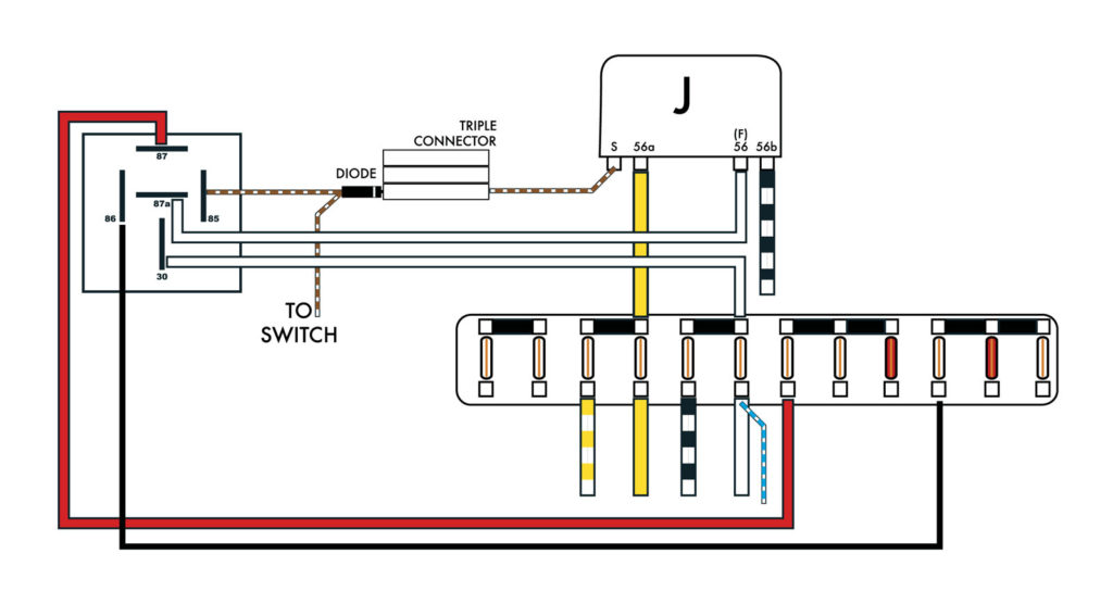
The black-and-white-striped wire from the harness goes to the negative terminal. The white wire is black and connects to the terminal opposite. The black wire is connected to the contact breaker. To verify the connection, use a paperclip or a pencil to pull them out from the plug housing. Check that you don’t bend the connectors.
Accessory terminals
Diagrams of ignition wiring show the various wires utilized to power various components. There are usually four different colored terminals for each component. Red is used for accessories while yellow is the battery, while green is the solenoid for starters. The “IGN” terminal allows you to start the car, manage the wipers, and any other operation features. The diagram shows how to connect the ACC and ST terminals to the rest of the components.
The terminal BAT connects the battery to the charger. The electrical system won’t start without the battery. The switch won’t be able to turn on if the battery isn’t present. If you’re not sure of the exact location where the battery in your car is situated, you can examine your wiring diagram to figure out where it is. The accessory terminals in your vehicle are connected to the battery and the ignition button. The BAT terminal is connected to the battery.
Some ignition switches come with the option of an “accessory position” that allows users to adjust their outputs independently of the ignition. Some customers prefer to make use of an additional output independent of the ignition. To make use of the auxiliary output, connect the connector with the same colors as the ignition connecting it to the ACC terminal on the switch. This convenience feature is great however, there’s one difference. The majority of ignition switches have an ACC position if the car is in the ACC, but they’ll be in the START position when the vehicle is IGN.
Gallery of Vw Electronic Ignition Wiring Diagram
Gallery of Vw Electronic Ignition Wiring Diagram


