Walker Mower Ignition Switch Wiring Diagram – Let’s first examine the various terminals that are used in the ignition switch. These terminals are for the Ignition button, Coil and Accessory. Once we know what these terminals do then we can identify the different parts in the ignition wiring. In addition, we will discuss the functions of the Ignition switch and Coil. Then, we’ll talk about the function of the Ignition switch and Coil.
The terminals of the ignition switch
An ignition switch has three switches that supply the battery’s power to various destinations. The first switch is the one that supplies the choke with power, while the second toggles the on/off status of the ignition switch. Different manufacturers use different color-coding systems that correspond to the conductors. OMC utilizes the same system. The ignition switch also includes a connector for adding the timer.
Even though some of the ignition switch terminals might not be original, the numbers of the terminals may not match the diagram. Before plugging in the ignition switch, ensure that you check the continuity. A multimeter is a great tool to check the continuity. After you’re satisfied with the continuity, you can place the new connector. If your vehicle has an original ignition switch supplied by the factory (or an electrical loom), the wiring loom may differ from the one in your vehicle.
Understanding how ACC outputs connect to the auxiliary outputs inside your car is vital. The ACC terminals as well as the IGN terminals function as the primary connections to your ignition switch. The START and IGN connections are the most important connections for radio and stereo. The ignition switch switches the car’s engine ON and OFF. The ignition switch terminals on older vehicles are marked with the alphabets “ACC” as well as “ST” (for the individual magneto wires).
Terminals for coil
To identify the kind of ignition coil you need to know the step is to learn the terminology. You’ll see a number of connections and terminals on the basic wiring diagram for ignition which includes two primary as well as two secondary. The coils have a specific operating voltage. The first method of determining what type you’re using is to test the voltage of S1 the primary terminal. S1 should also be tested for resistance to determine whether it’s a Type B, B, or an A coil.
The coil’s low-tension side must be connected to the chassis positively. This is also the ground on the diagram of the ignition wiring. The high-tension supply delivers positively directly to spark plugs. To prevent noise the coil’s metal body must be connected to the chassis. It’s not necessary for electrical use. The wiring diagram for ignition will also outline the connection of the positive coil’s terminals. Sometimes, a defective ignition coil can be identified through a scan performed at an auto parts shop.
The black-and-white-striped wire from the harness goes to the negative terminal. The terminal for the negative is served by the black trace that’s joined to the white wire. The black wire connects to the contact breaker. If you’re not certain about the connection between the twowires, use a paper clip to remove them from the plug housing. Be sure to verify that the connections aren’t bent.
Accessory terminals
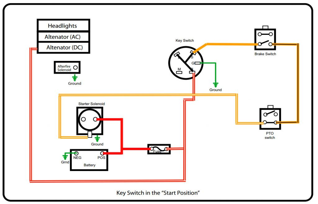
The ignition wiring diagrams illustrate the various wires that provide power to the various parts of the vehicle. There are usually four colored terminus lines for each component. Red refers to accessories, yellow the battery, and green the starter solenoid. The “IGN terminal lets you start the car, manage the wipers, and any other features that operate. This diagram demonstrates how to connect ACC and ST terminals to the other components.
The terminal BAT connects the battery to the charger. Without the battery, the electrical system does not get started. Additionally, the switch won’t begin to turn on. You can refer to your wiring diagram if you’re unsure where your car’s batteries are located. The ignition switch is connected to the car’s battery. The BAT terminal is connected with the battery.
Certain ignition switches come with an additional position in which users can modify their outputs and manage them without having to turn on the ignition. Some customers might want to utilize the auxiliary output separately from the ignition. You can use the additional output by connecting it to the ACC terminal on your switch using the same colors. This is an excellent option, but there’s one important difference. Some ignition switches are set to have an ACC position when the vehicle has moved into the ACC position. They’ll also be in the START mode once the vehicle is entered the IGN position.
Gallery of Walker Mower Ignition Switch Wiring Diagram
Gallery of Walker Mower Ignition Switch Wiring Diagram


