Westwood Ignition Switch Wiring Diagram – The first step is to take a look at the different types of terminals used on the ignition switch. These terminals serve for the Ignition button, Coil and Accessory. Once we know the terminals that are utilized, we can begin to determine the various components of the Westwood Ignition Switch Wiring Diagram. In addition, we will discuss the different functions of the Ignition Switch and Coil. Following that, we’ll shift our attention to Accessory terminals.
Terminals for the ignition switch
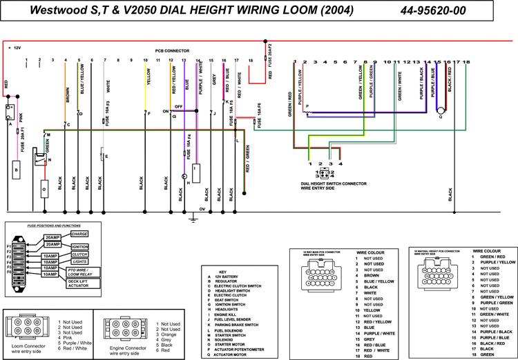
There are three separate switches in an ignition switch, which transmit the battery’s current voltage to several different locations. The first one supplies the choke with power when pushed, and the second is the ignition switch’s ON/OFF position. Different manufacturers have different colors-coding systems to match the conductors. OMC uses the same method. The ignition switch comes with an option to connect the tachometer.
While many ignition switch terminals do not come in original form however, the numbers may not match the diagram. To ensure that your wires are plugged in to the switch it is recommended to check their continuity. You can check this using a simple multimeter. When you’re happy with the connection it’s time to connect the new connector. If you’re using an ignition switch supplied by the manufacturer, the wiring loom is different from the one you have in your car.
Understanding how ACC outputs are connected to the other outputs of your vehicle is crucial. The ACC and IGN connectors are the standard connections of the ignition switch. While the START, IGN, and ACC terminals are the primary connections for the radio or stereo, the START/IGN terminals are the main ones. The ignition switch regulates the engine in your car. The terminals for the ignition switch on older vehicles are marked with the initials “ACC” and “ST” (for each magneto wires).
Terminals for coil
The language used to decide the kind and model of the ignition coil is the primary thing. In a simple ignition wiring diagram there are several different connections and terminals, which include two primary and two secondary. Each coil is operating at a certain voltage. The first step in determining which type you’re dealing with is to test the voltage on S1, or the primary terminal. S1 should be tested for resistance in order to identify if the coil belongs to type A, B and/or C.
The negative of the chassis must be connected to the side of low-tension. This is what you see in the diagram of wiring. The high-tension part provides the spark plugs with positive. For suppression purposes the coil’s body metal must be connected with the chassis. It is not required for electrical use. The diagram of the ignition wiring will also indicate the connection of the positive coil’s terminals. There could be an ignition coil problem which can be identified by looking it up at the auto parts shop.
The black-and-white-striped wire from the harness goes to the negative terminal. The other white wire has a black trace on it, and it goes to the positive terminal. The black wire connects to the contact breaker. To test the wires’ connections use a paperclip to lift them from the housing. Also, make sure to ensure that the terminals have not been bent.
Accessory terminals
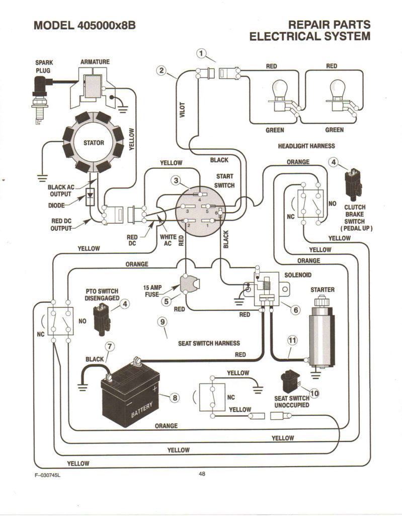
Diagrams of ignition wiring show the wires used in the power supply of the vehicle. Each component has four distinct colored connections. The red color represents accessories, yellow for the battery and green is for the starter solenoid. The “IGN” terminal can be used to start the car , and also to operate the wipers as well as other operational functions. The diagram below illustrates how to connect the ACC terminal and ST terminals to the other components.
The terminal BAT is the connector for the battery. Without the battery, the electrical system does not begin. The switch will not turn on if the battery isn’t present. It is possible to refer to your wiring diagram if you’re uncertain about where the car’s batteries are. The ignition switch is connected to the car’s battery. The BAT connector connects to your battery.
Certain ignition switches have an additional “accessory” position, in which users can manage their outputs without the ignition. Sometimes, customers wish to use an auxiliary output that is separate from the ignition. You can utilize the additional input by connecting the connector to the ACC terminal. This feature of convenience is fantastic however there’s a differentiator. The majority of ignition switches are set to have an ACC position when the car is in the ACC position, but they’re set to the START position when the car is in the IGN position.
Gallery of Westwood Ignition Switch Wiring Diagram
Gallery of Westwood Ignition Switch Wiring Diagram


