Wiring Diagram Boat Ignition Switch – We will first look at the various types and purposes of the terminals found in the ignition switches. These are terminals for Coil, Ignition Switch, and Accessory. Once we’ve determined the function of these terminals, we can recognize the various parts of the ignition wiring. We’ll also be discussing the function of the Ignition switch and Coil. Then we’ll discuss the Accessory Terminals.
The terminals of the ignition switch
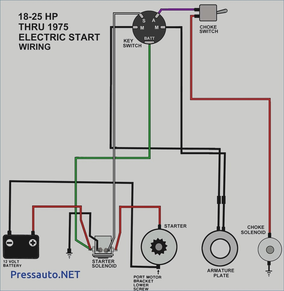
The ignition switch has three switches. They supply the voltage of the battery to many different places. The choke is powered by the first switch. The second switch controls the ON/OFF of the ignition switch. Different manufacturers use different colour-coding systems that correspond to the conductors. OMC utilizes the same system. The connector allows for the attachment of a speedometer the ignition switch.
Although the majority of ignition switch terminals are duplicated, the number may not be consistent with the diagram. It is important to first verify the integrity of the wires to determine if they’re plugged into the ignition switch in the correct way. A multimeter that is inexpensive can assist you in this. Once you’re satisfied with the quality of the connection then you can connect the new connector. If you’re using an ignition switch supplied by the manufacturer, the wiring loom is different from the one in your car.
Before connecting the ACC outputs to the auxiliary outputs of your car it is crucial to know the fundamentals of these connections. The ACC/IGN connections function as the default connections for the ignition switch. The START/IGN connections connect to the stereo or radio. The ignition switch is the one that turns the engine of your car to and off. The ignition switch terminals on older cars are labeled with the initials “ACC” and “ST” (for the individual magneto wires).
Terminals for coil
Understanding the terms that is used is the first step to finding out the right type of ignition coil. The fundamental diagram of ignition wiring illustrates a variety of connections and terminals. There are two primary and secondary connections. Each coil has an operating voltage. The first step in determining which kind of coil you’re dealing with is to test the voltage at S1 or the primary terminal. S1 must be examined for resistance to identify if the coil belongs to Type A, B, and/or C.
The negative end of the chassis end should be connected to the coil’s low-tension end. This is the ground on the wiring diagram for ignition. The high tension side provides positive power directly to the spark plugs. The body of the coil has to connect to the chassis to suppress the effect, but it is not electrically required. The wiring diagram for ignition will also indicate the connection of the positive coil’s terminals. In some instances you’ll discover that an ignition coil that is malfunctioning is identified by scans in an auto parts store.
The black-and-white-striped wire from the harness goes to the negative terminal. The terminal that is negative is served by the black trace attached to the white wire. The black wire is connected to the contactbreaker. You can check the connections using a paperclip to pull the wires out from the housing. Make sure that the connectors don’t bend.
Accessory terminals
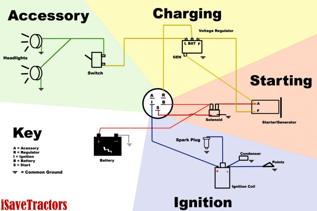
Diagrams of ignition wiring depict the wires used to provide power to various components of the vehicle. There are generally four color-coded terminals that correspond to each component. For accessories, red is for starter solenoid, yellow for battery, and blue is for accessory. The “IGN” terminal is used to turn on the vehicle and control the wipers as well as other operational functions. This diagram demonstrates how to connect ACC and ST terminals to the rest of components.
The battery is attached to the terminal called BAT. The electrical system cannot start without the battery. In addition, the switch will not begin to turn on. To find the battery in your car look over your wiring diagram. The accessory terminals on your vehicle connect to the battery and the ignition switch. The BAT connector is connected to your battery.
Some ignition switches are equipped with an accessory position. This allows users to connect their outputs to another location without the ignition. In some cases, users may want to use the auxiliary input separately from the ignition. To allow the auxiliary output to be used, wire the connector in the same color as that of the ignition. Then , connect it to the ACC end of the switch. Although this is a useful feature, there’s one crucial distinction. Some ignition switches are set to have an ACC position once the car has been moved into the ACC position. They will also be in the START position once the vehicle is entered the IGN position.
Gallery of Wiring Diagram Boat Ignition Switch
Gallery of Wiring Diagram Boat Ignition Switch


