Wiring Diagram For Johnson Outboard Ignition Switch – Let’s begin by looking at the various types terminals found on an ignition switch. These are the terminals that connect the Ignition, Coil, or Accessory. Once we understand the function of each type of terminal, it is possible to identify the parts of the ignition wiring. In addition, we will discuss the roles of the Ignition switch and Coil. We will then turn our attention towards the accessories terminals.
Terminals for ignition switch
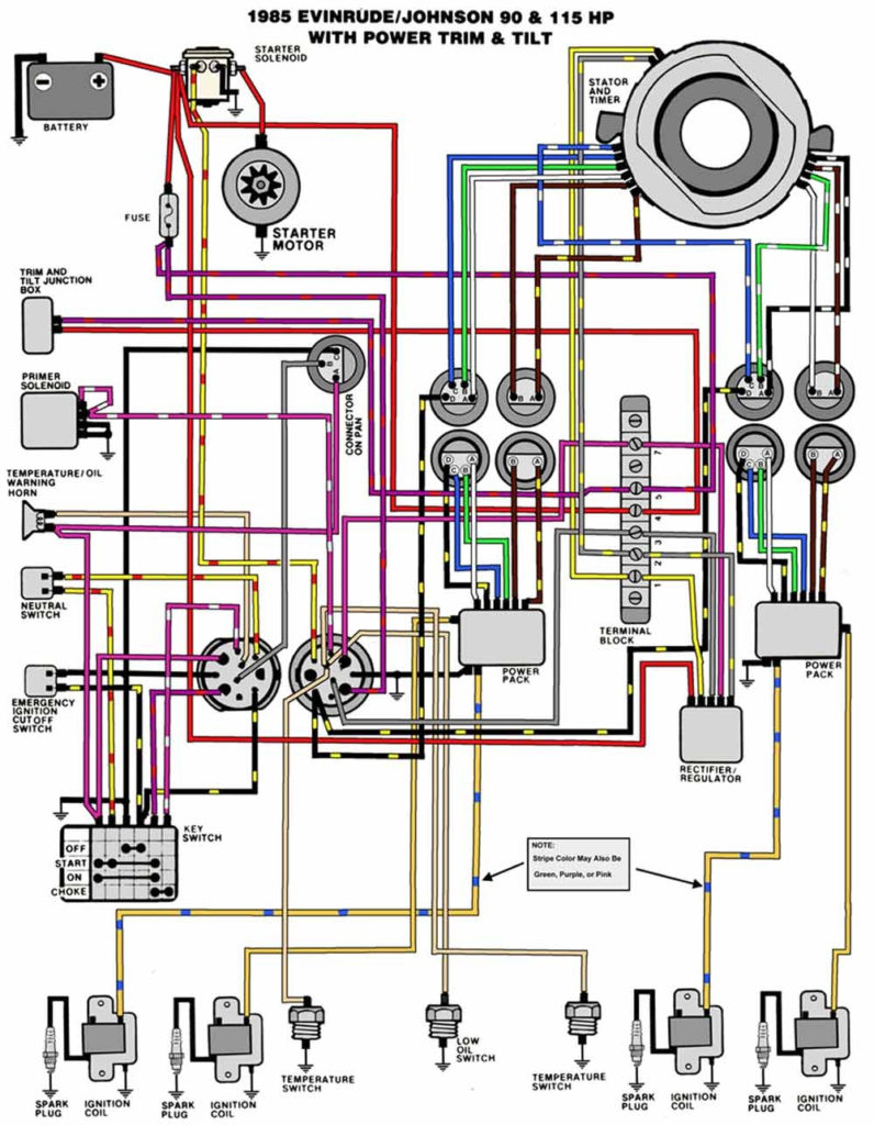
Three switches are found in an ignition switch. Each of these three switches transmits the battery’s current to several different places. The first switch is used to power the choke through pushing it, and the second is for the ON/OFF setting. Different manufacturers use different color-coding methods for different conductors. We will cover this in a different article. OMC utilizes this approach. Connectors can be attached to the ignition switch to add the digital Tachometer.
While most ignition switch terminals can be duplicated, the number may not be in line with the diagram. Examine the integrity of the wires first to ensure that they’re connected correctly to the ignition switch. A multimeter is a great instrument to verify the continuity. After you’re satisfied with the continuity then you can connect the new connector. If your car is equipped with an original ignition switch supplied by the factory (or an electrical loom), the wiring loom may differ from that in the car.
For connecting the ACC outputs to the auxiliary outputs of your vehicle, you have to first understand the way these two connections function. The ACC terminals as well as the IGN terminals serve as the primary connections to the ignition switch. The START and IGN connections are the main connections for stereo and radio. The ignition switch switches the engine of your car ON and OFF. Older cars are equipped with ignition switch terminals labeled “ACC” or “ST” (for individual magnetowires).
Terminals for coil
Understanding the terms is the initial step to knowing what type of ignition coil you have. The diagram of the basic ignition wiring depicts various connections and terminals. There are two primary and one secondary. Each coil has an operating voltage. The first step to determine the kind you’re dealing with is to test the voltage at S1 or the primary terminal. Also, you should examine S1 for resistance in order to identify if it’s an A or B coil.
The chassis’ negative needs to be connected to the side of low-tension. This is exactly what you can see in the diagram of wiring. The high-tension part supplies positive direct to the sparkplugs. The metal body of the coil needs to be connected to the chassis for suppression purposes, but it is not electrically essential. The wiring diagram of the ignition will explain how to connect the terminals of either the negative or positive coils. Sometimes, a damaged ignition coil is identified with a scan at an auto parts shop.
The black-and-white-striped wire from the harness goes to the negative terminal. The white wire is the other one. It is black with a trace on it and it goes to the positive terminal. The contact breaker is linked to the black wire. To check the connection, make use of a paperclip or pencil to remove them of the housing for the plug. Be sure that you don’t bend the connectors.
Accessory terminals
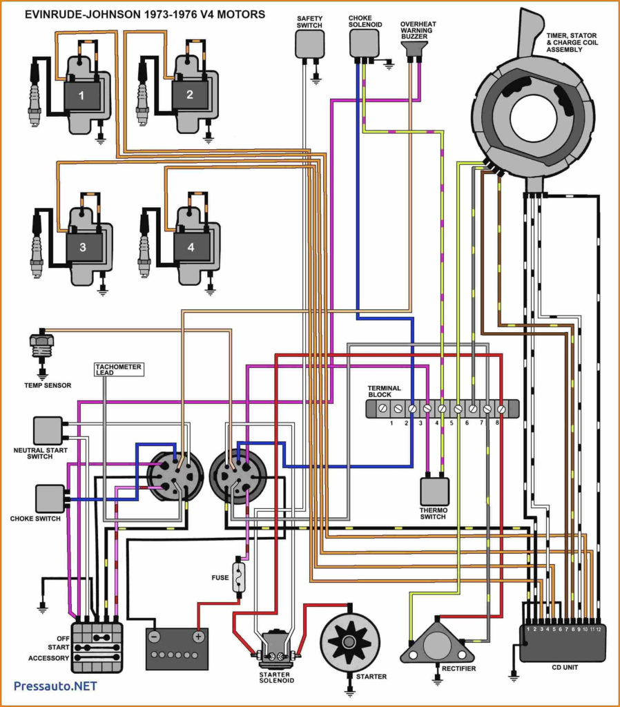
The diagrams for ignition wiring illustrate the wires that are used to power the vehicle’s electrical supply. There are generally four color-coded terminals that correspond to the respective component. Red stands for accessories, yellow for the battery, and green for the starter solenoid. The “IGN” terminal can be used to start the car, control the wipers, as well as other functions. The below diagram shows how to connect the ACC terminal and ST terminals to the other components.
The terminal BAT connects the battery to the charger. The electrical system is not able to begin without the battery. Furthermore, the switch won’t start. You can view your wiring diagram to determine where your car’s batteries are located. The accessory terminals on your vehicle are connected to the battery as well as the ignition switch. The BAT terminal is connected with the battery.
Some ignition switches have an “accessory” position that allows users to control their outputs without having to use the ignition. Customers may want to use the auxiliary output in addition to the ignition. Use the auxiliary output by connecting the connector to the ACC terminal on your switch that has the same color. This is a great convenience feature however there’s a distinction. Some ignition switches are configured to be in an ACC position when the vehicle has moved into the ACC position. They’ll also be in START mode once the vehicle is moved into the IGN position.
Gallery of Wiring Diagram For Johnson Outboard Ignition Switch
Gallery of Wiring Diagram For Johnson Outboard Ignition Switch


