Wiring Diagram For Mercury Ignition Switch – In the beginning, we’ll examine the various types of terminals found in the ignition switch. These include the terminals for the Ignition switch, Coil, and Accessory. After we’ve established what these kinds of terminals are for, we will proceed to identify the different parts of the Wiring Diagram For Mercury Ignition Switch. In addition, we will discuss the function of the Ignition switch and Coil. The next step is to focus to the accessory terminals.
Terminals for ignition switches
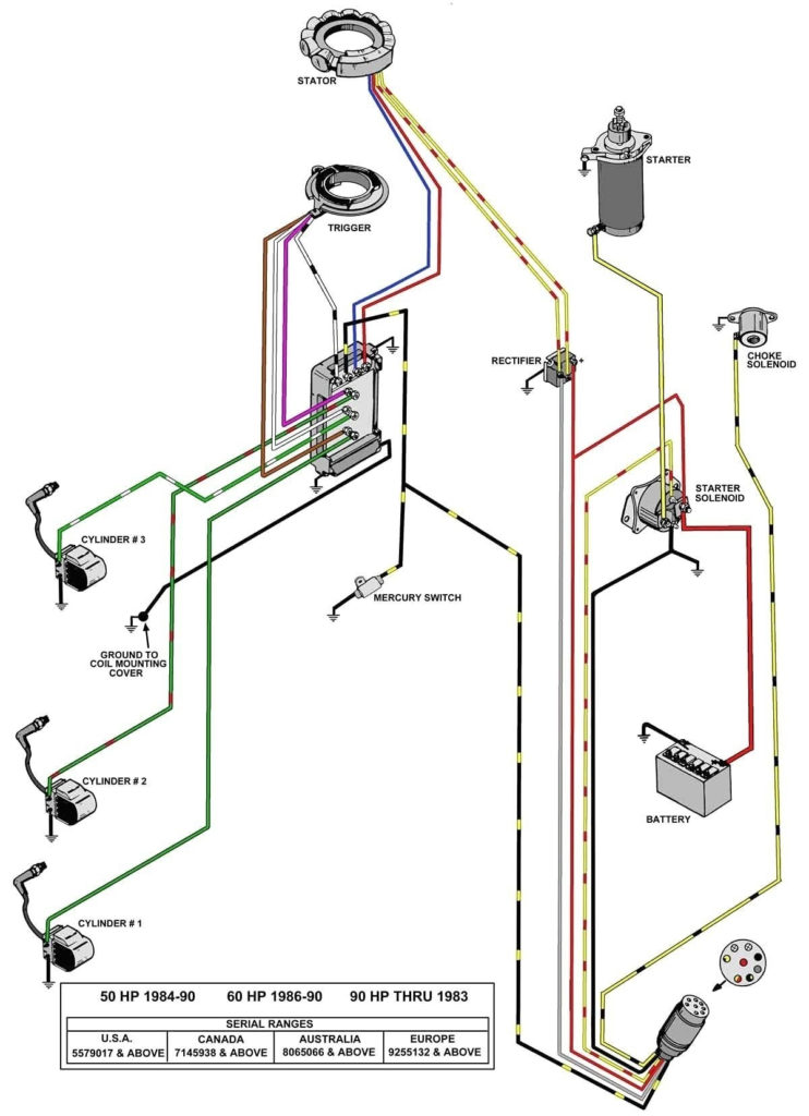
An ignition switch is composed of three different switches. They are the ones that supply the battery’s power to several destinations. The first switch supplies power to the choke whenever it is pushed. The second is the position of the ignition switch’s ON/OFF. Every manufacturer has its own color-coding system, which we will discuss in another article. OMC utilizes this approach. The connector allows for the attachment of a speedometer the ignition switch.
Although the majority of ignition switch terminals can be duplicated, the number may not be consistent with the diagram. Examine the continuity of the wires first to make sure they’re connected correctly to the ignition switch. You can check this using a simple multimeter. After you’re happy with the continuity of the wires, then you’ll be able to connect the new connector. If your car has an installed ignition switch, the wiring diagram will differ.
It is essential to know how the ACC outputs and auxiliary outputs function in order to connect them. The ACC and IGN terminals are the default connections on the ignition switch. the START and IGN terminals are the main connections to the radio and stereo. The ignition switch turns the car’s engine ON and OFF. Older cars are identified by the initials “ACC”, “ST”, (for individual magneto cables) at their ignition switch’s terminals.
Terminals for coil
Understanding the terms is the first step towards knowing what type of ignition coil you’ve got. The diagram of the basic ignition wiring illustrates a variety of connections and terminals. There are two primary and one secondary. The coils come with a distinct operating voltage, and the first step to determine which one you’ve got is to check the voltage at S1, the main terminal. S1 should be checked for resistance to identify if the coil is Type A, B, and/or C.
The negative end of the chassis must be connected to the coil’s low-tension side. This is exactly what you can see on the diagram of wiring. The high-tension side delivers the positive power direct to the spark plugs. For suppression purposes the coil’s metal body must be connected with the chassis. It is not required for electrical use. The diagram of the ignition wiring will also indicate the connections of the positive coil terminals. In certain instances scanning your local auto parts shop will help identify the malfunctioning ignition coils.
The black-and-white-striped wire from the harness goes to the negative terminal. The white wire has a black color and connects to the negative terminal. The contact breaker is connected to the black wire. You can check the connections with a paperclip to remove the wires from the housing. Check that the terminals aren’t bent.
Accessory terminals
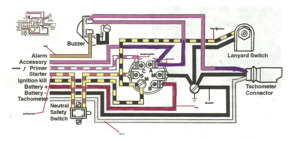
The wiring diagrams for the ignition show the different wires that are used to power various components of the vehicle. There are typically four color-coded terminals that correspond to each component. The red symbol represents accessories, yellow represents the battery, and green for the solenoid for starters. The “IGN terminal” is used to power the wipers and other operating functions. The diagram demonstrates how to connect the ACC and ST terminals to the other components.
The terminal BAT is the connector for the battery. The battery is essential for the electrical system to begin. A dead battery can cause the switch to stop turning on. To locate your car’s battery look over your wiring diagram. The accessory terminals of your car are connected with the battery and the ignition button. The BAT terminal is connected to the battery.
Certain ignition switches have an additional position in which users can alter their outputs and control them without needing to use the ignition. Sometimes, customers want to utilize an additional output that is independent of the ignition. For the auxiliary output to be used, wire the connector in the same color as the ignition. Then connect it with the ACC end of the switch. This option is useful, but it has one major distinction. Most ignition switches will have an ACC position if the car is in ACC, but they’ll be at the START position when the vehicle is in IGN.
Gallery of Wiring Diagram For Mercury Ignition Switch
Gallery of Wiring Diagram For Mercury Ignition Switch


