Wiring Diagram For Universal Ignition Switch – The first step is to take a look at the different kinds of terminals that are used on the ignition switch. These are terminals for the Ignition, Coil, or Accessory. After we’ve established what these types of terminals are used for, we will proceed to discover the various components of the Wiring Diagram For Universal Ignition Switch. We’ll also go over what functions are available for the Ignition switch and the Coil. After that, we will concentrate on the accessories terminals.
Terminals for ignition switches
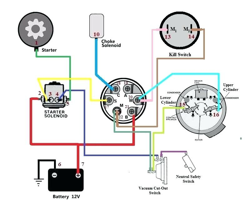
There are three separate switches on an ignition switch, which transmit the battery’s current voltage to various places. The first switch provides power to the choke when it is pushed. The second is the switch that controls the ignition’s ON/OFF positions. Different manufacturers have different colour-coding systems that correspond to the conductors. OMC utilizes the same system. Connectors can be connected to the ignition switch in order to connect the digital tachometer.
Although the majority of ignition switch terminals do not have an original number, they may be equipped with a different number. Check the electrical continuity first to make sure they’re properly connected to the ignition switch. This can be accomplished using an inexpensive multimeter. Once you are satisfied that all wires are running in good harmony and you are able to connect the new connector. If your car has an original ignition switch supplied by the factory (or an electrical loom) The wiring loom will differ from that in your car.
For connecting the ACC outputs to the auxiliary outputs of your car, you need to understand how these two connections work. The ACC/IGN terminals act as the default connections on the ignition switch. The START/IGN connections connect to the radio or stereo. The ignition switch turns the car’s engine on and off. Older cars have the ignition switch terminals labeled “ACC” or “ST” (for individual magnetowires).
Terminals for coil
Understanding the terms that is used is the initial step to finding out the right kind of ignition coil to choose. A basic diagram of the wiring will provide you with a range of connections and terminals. Each coil is operating at a certain voltage. The first step to determine which kind you have is to check the voltage at S1 or the primary terminal. To determine if it is an A, C or B coil it is recommended to also test S1’s resistance.
The coil’s low-tension side should be connected at the chassis’ minus. This is the ground of the wiring for ignition. The high tension part supplies positive power directly to the spark plugs. It is necessary for the purpose of suppression that the metallic body of the coil is connected to the chassis, but not essential. The diagram of the ignition wiring will also reveal the connection of the positive and negative coil’s terminals. In some cases it is recommended to conduct a scan at the local auto parts store will be able to diagnose malfunctioning ignition coils.
The black-and-white-striped wire from the harness goes to the negative terminal. The white wire also has a black trace on it and connects to the positive terminal. The black wire connects to the contact breaker. You can take the black wire from the plug housing by using a paperclip if you are unsure about the connections. You should also check to make sure that the connections are not bent.
Accessory terminals
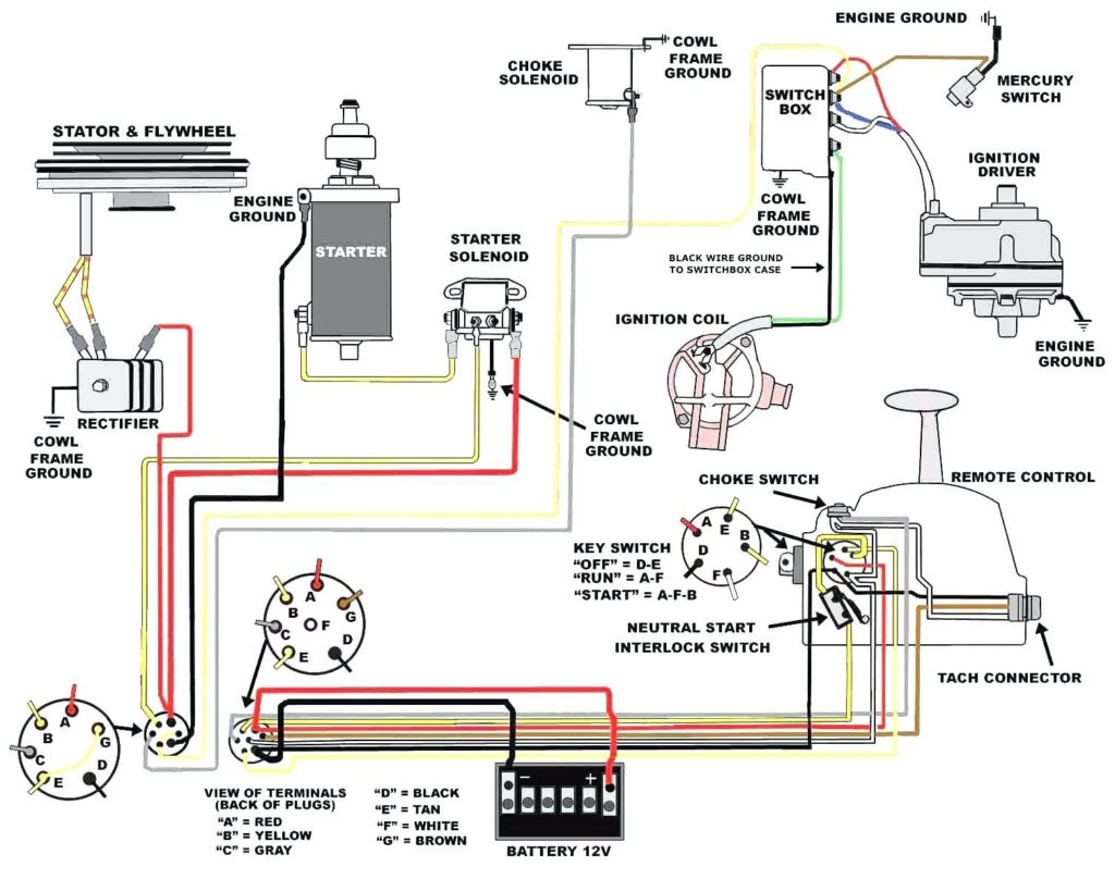
The wiring diagrams of the ignition illustrate the different wires used to power the various components of the vehicle. Each component is equipped with four distinct color-coded connections. Red is for accessories, yellow is for the battery, while green is the solenoid for starters. The “IGN terminal” is used to run the wipers, as well as other operating functions. The diagram shows how to connect ACC or ST terminals, and other.
The terminal called BAT is the location where the battery is. Without the battery the electrical system can not begin. Furthermore, the switch won’t begin to turn on. If you’re not sure where your car’s battery is located, you can review the wiring diagram of your car to determine where it is. The accessory terminals on your vehicle are connected to the battery and the ignition switch. The BAT Terminal is connected to the battery.
Certain ignition switches come with an “accessory” setting that permits users to control their outputs , without needing to turn on the ignition. Sometimes, customers want to utilize an additional output independent of the ignition. To allow the auxiliary output to be used, wire the connector to the same color as the ignition. Then connect it with the ACC end of the switch. This feature is convenient however, it does have one key differentiator. Most ignition switches will have an ACC position when the vehicle is in ACC however they’ll be in the START position when the vehicle is IGN.
Gallery of Wiring Diagram For Universal Ignition Switch
Gallery of Wiring Diagram For Universal Ignition Switch


