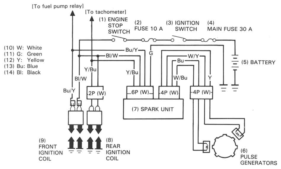
04 Shadow 600 Ignition Coil Wiring Diagram – In the beginning, we’ll examine the various types of terminals found on the ignition switch. These terminals comprise the Ignition switch, the Coil as well as the Accessory. Once we know what these terminals are, we will determine the various components in the ignition wiring. We’ll also discuss the functions of the Ignition switch and Coil. After that, we’ll turn our attention to the Accessory terminals.
Terminals for ignition switches
The ignition switch is comprised of three separate switches that feed the battery’s power to various locations. The first switch is the one that supplies the choke with power, while the second toggles the ON/OFF status of the ignition switch. Different manufacturers use their own color-coding systems for different conductors which is explained in a different article. OMC follows the same system. A tachometer adapter is installed on the ignition switch to allow the addition of a tachometer.
Although the majority of ignition switch terminals do not have an original number, they might have a different one. To make sure that the wires are correctly plugged in to the ignition switch it is recommended to check their continuity. You can check this using an inexpensive multimeter. When you’re satisfied with the continuity of your wires, you’ll be able to install the new connector. If your car has an ignition switch installed the wiring diagram will differ.
You must first understand how the ACC outputs and auxiliary outputs work in order to connect them. The ACC and IGN terminals are the default connection on your ignition switch, and the START and IGN terminals are the principal connections for the radio and stereo. The ignition switch is responsible for turning the engine of your car on and off. The terminals for the ignition switch on older vehicles are marked with the initials “ACC” as well as “ST” (for the individual magneto wires).
Coil terminals
The first step in determining the type of ignition coil is to know the terms used. The diagram of the basic ignition wiring shows a number different connections and terminals. There are two primary and one secondary. The coils are equipped with a particular operating voltage. The first step in determining which type you’re using is to test the voltage at S1, the main terminal. S1 must also be inspected for resistance in order to identify if the coil is an A, Type B, or an A coil.
The chassis’ negative must be connected to the side of low-tension. This is the ground of the wiring for ignition. The high-tension part supplies the spark plugs with positive. It is necessary for suppression purposes that the body of the coil’s metal be connected to the chassis, however it isn’t essential. You will also see the connections of the positive and the negative coil terminals on the diagram of the ignition wiring. Sometimes, a defective ignition coil is identified by a scan done in an auto parts shop.
The black-and-white-striped wire from the harness goes to the negative terminal. The terminal that is negative is served by the trace in black that’s attached to the white wire. The black wire goes to the contact breaker. You can check the connections with a pencil to pull the wires out of the housing. Also, make sure that the connections aren’t bent.
Accessory terminals
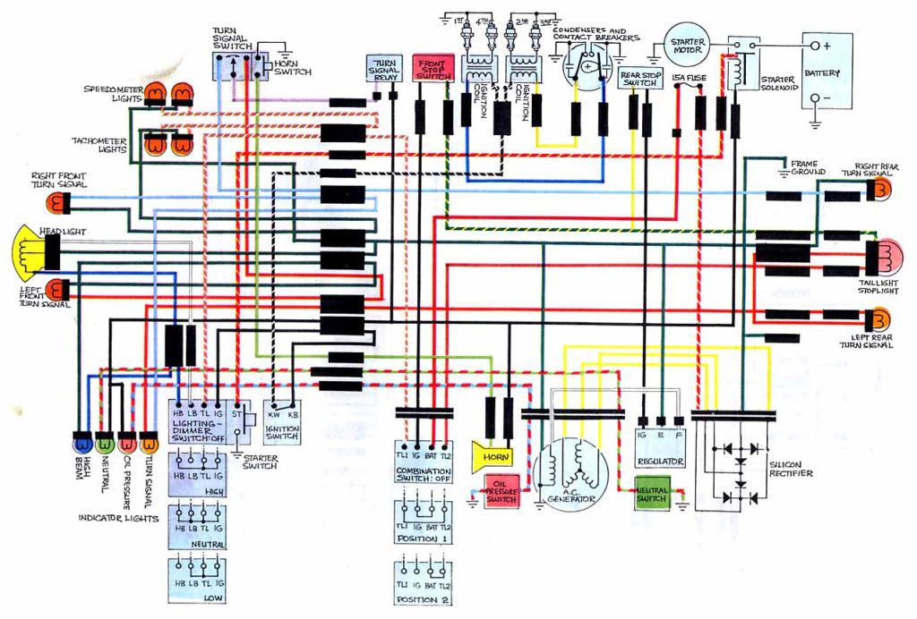
The ignition wiring diagrams illustrate the different wires used to provide power to the various parts of the vehicle. There are generally four colors-coded terminus of each part. The red color is used for accessories, yellow is for the battery, while green is for the starter solenoid. The “IGN” terminal can be used to start the car, control the wipers and other features. The diagram illustrates how to connect ACC or ST terminals and the rest.
The terminal BAT is the connection for the battery. The electrical system can’t be started without the battery. A dead battery could cause the switch to not come on. If you’re not sure of the location of your car’s battery situated, look at your wiring diagram to see where it is. The accessory terminals in your car are connected to the ignition switch as well as the battery. The BAT connector connects to your battery.
Some ignition switches offer an additional “accessory position” that allows users to adjust their outputs independently of the ignition. Some customers may prefer to utilize the auxiliary output in addition to the ignition. In order for the auxiliary output be used, plug in the connector in the same shade as the ignition. Connect it to the ACC end of the switch. While this is a convenient feature, there is one crucial distinction. Most ignition switches are configured to operate in the ACC position when the vehicle is in the ACC position, while they’re in the START position when the vehicle is in the IGN position.
Gallery of 04 Shadow 600 Ignition Coil Wiring Diagram
Gallery of 04 Shadow 600 Ignition Coil Wiring Diagram


