05 Kawasaki 636 Ignition Wiring Diagram – First, we will take a look at the various kinds of terminals that are found on the ignition switch. These include the terminals for the Ignition switch, Coil, and Accessory. When we have a clear understanding of the purpose of each kind of terminal, we can then identify the various components of the ignition wiring. We will also talk about the functions and the Coil. Then, we’ll talk about the functions of the Ignition switch and Coil.
Terminals for ignition switches
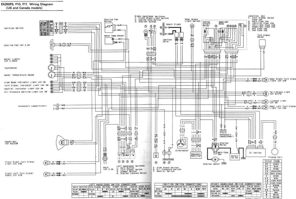
Three switches are located on the ignition switch. Each of these three switches transmits the battery’s current to various locations. The first switch powers the choke. The second switch is responsible for the ON/OFF of the ignition switch. Different manufacturers have different color-coding schemes for different conductors. We will cover this in another article. OMC uses this system. The ignition switch also includes an adapter for the addition of a timer.
While many ignition switch terminals might not be authentic, the numbering of each one might not be in line with the diagram. Before you plug in the ignition switch, ensure that you check the continuity. This can be checked using an inexpensive multimeter. Once you are happy with the continuity of the wires it is time to install the new connector. The wiring loom in an ignition system switch that is supplied by the manufacturer differs.
Before connecting the ACC outputs to your car’s auxiliary outputs it is crucial to understand the basics of these connections. The ACC/IGN connections function as the default connection on the ignition switch. The START/IGN connections connect to the radio or stereo. The ignition switch is the engine’s switch to turn off or on. In older vehicles the ignition switch’s terminals are marked with the initials “ACC” and “ST” (for the individual magnet wires).
Terminals for coil
The terminology used to determine the kind and model of the ignition coil is the first thing. You’ll see a number of connections and terminals in the basic wiring diagram for ignition that include two primary and two secondary. The voltage that operates on each coil differs. This is why it is crucial to test the voltage at S1 (primary terminal). You should also test S1 for resistance in order to determine whether it is an A B, C, or coil.
The coil’s low-tension side should be connected at the chassis’ minus. This is also the ground on the ignition wiring diagram. The high-tension side provides positive direct to the sparkplugs. To prevent noise, the coil’s body metal must be connected with the chassis. This is not necessary for electrical use. The wiring diagram will show the connection between the positive and negative coil terminals. Sometimes, a visit to an auto parts shop can detect a defective ignition wire.
The black-and-white-striped wire from the harness goes to the negative terminal. The white wire is the other one. It has a black trace on it and it connects to the positive terminal. The contact breaker is connected to the black wire. You can remove the black wire from the plug housing with a paper clip if you are unsure about the connection. It is also important to see that the terminals aren’t bent.
Accessory terminals
Ignition wiring diagrams show the various wires utilized to power the vehicle’s various components. There are generally four color-coded terminals to each component. The accessories are red, the battery is yellow the starter solenoid green. The “IGN” terminal can be utilized to turn on the car, control the wipers, and other features. This diagram shows how to connect ACC and ST terminals to the rest of the components.
The terminal BAT connects the battery to the charger. The battery is necessary to allow the electrical system to start. Additionally, the switch will not turn on without the battery. It is possible to refer to your wiring diagram if you’re unsure where your car’s batteries are located. The accessory terminals in your car are connected with the battery and the ignition button. The BAT terminal connects to the battery.
Some ignition switches have an “accessory” setting that permits users to control their outputs , without needing to utilize the ignition. In some cases, users may want to use the auxiliary input independently of the ignition. You can use the auxiliary output by connecting the connector to the ACC terminal on the switch that has the same color. This feature of convenience is fantastic, but there is one distinction. Some ignition switches are programmed to have an ACC position when the vehicle has been moved into the ACC position. They’ll also be in the START position when the vehicle has moved into the IGN position.
Gallery of 05 Kawasaki 636 Ignition Wiring Diagram
Gallery of 05 Kawasaki 636 Ignition Wiring Diagram


