1018 Series Hot Surface Ignition Wiring Diagram – We will first look at the various types and purposes of the terminals that are found in the ignition switches. These are terminals for the Ignition, Coil, or Accessory. Once we have established the purpose of these terminals are used for, we will proceed to determine the various parts of the 1018 Series Hot Surface Ignition Wiring Diagram. We will also cover the functions of both the Ignition Switch and Coil. Then, we will focus on the accessory terminals.
Terminals for ignition switches
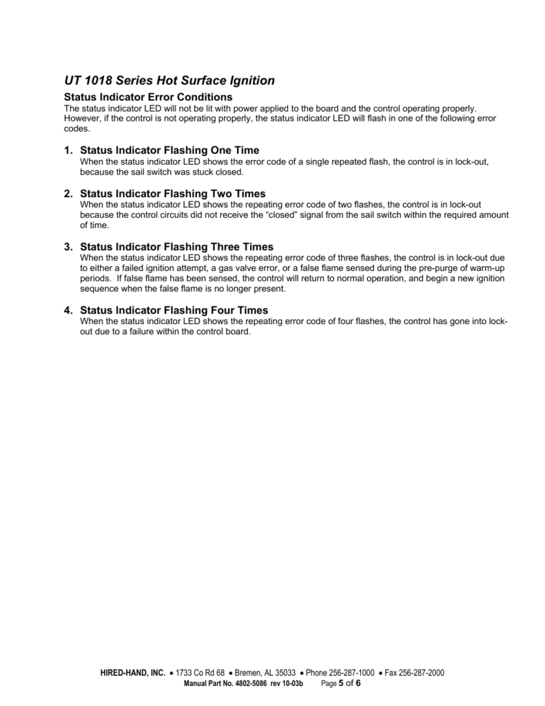
An ignition switch has three switches that supply the battery’s power to various locations. The first switch is the one that supplies power to the choke, while the second toggles the state of the switch. Each manufacturer has their individual color-coding system that we’ll discuss in a subsequent article. OMC uses this method. The ignition switch comes with a connector for adding the timer.
Although the majority of ignition switch terminals are duplicated, the numbers might not match the diagram. It is important to first verify the integrity of the wires to see if they are plugged into the ignition switch correctly. A multimeter that is inexpensive can assist you in this. Once you are satisfied that all wires are in good continuity, you can attach the new connector. The wiring loom of the ignition switch supplied by the manufacturer will differ from the one that you have in your car.
Understanding how ACC outputs are connected to the other outputs in your car is vital. The ACC/IGN terminals act as the default connection on the ignition switch. The START/IGN terminals are connected to the stereo or radio. The ignition switch is the engine’s off/on button. The terminals of older vehicles’ ignition switches are labeled with “ACC” and ST (for the individual magneto wires).
Terminals for coil
To determine the type of ignition coil, the first step is to learn the definition of. A basic diagram of the wiring will show you a number of connections and terminals. You need to determine the kind of coil you have by testing the voltage at the primary terminal, S1. S1 must also be subjected to resistance tests to determine if it’s a Type A or B coil.
The chassis’ negative must be connected to connect the coil’s low-tension end. This is what is known as the ground for the wiring for ignition. The high-tension component connects the spark plugs to a positive. The body of the coil has to be connected to the chassis for suppression purposes, but it is not electrically essential. The diagram of the ignition wiring will also show you how to connect the negative and positive coil’s terminals. Sometimes, a visit to an auto part store can identify a problem with the ignition wire.
The black-and-white-striped wire from the harness goes to the negative terminal. The negative terminal is served by the black trace attached to the white wire. The contact breaker is linked to the black wire. It is possible to remove the black wire from the housing of the plug by using a paperclip If you’re unsure of the connections. Be sure to ensure that the terminals haven’t been bent.
Accessory Terminals

The wiring diagrams of the ignition illustrate the various wires that power the various components of the car. Typically there are four color-coded terminals for each component. The accessories are colored red, the battery is yellow, the starter solenoid green. The “IGN” terminal can be used to start the car , and also to operate the wipers and other operating features. The diagram illustrates how you can connect ACC or ST terminals and the rest.
The battery is attached to the terminal whose name is BAT. The electrical system will not start if the battery isn’t connected. A dead battery can make the switch not come on. You can refer to your wiring diagram if you are unsure where your car’s batteries are located. The ignition switch is connected to the car’s battery. The BAT terminal is connected with the battery.
Certain ignition switches provide an additional “accessory position” which allows users to modify their outputs independent of the ignition. Some customers might want to use the auxiliary input independently of the ignition. Make use of the secondary output by connecting the connector to the ACC terminal on the switch using the same colors. This is an excellent option, but there’s an important distinction. Some ignition switches are configured to be in an ACC location when the car is in the ACC position. They also will be in the START position when the vehicle has entered the IGN position.
Gallery of 1018 Series Hot Surface Ignition Wiring Diagram

Gallery of 1018 Series Hot Surface Ignition Wiring Diagram


