12 Volt Ignition Wiring Diagram – First, we will examine the different types of terminals on the ignition switch. They include terminals for Coil, Ignition Switch, and Accessory. Once we’ve established the purpose of the terminals we can recognize the various parts of the ignition wiring. Then, we will discuss the functions for the Ignition switch and the Coil. Then, we’ll talk about the roles of the Ignition switch as well as Coil.
The terminals of the ignition switch
An ignition switch contains three separate switches that feed the battery’s current to different destinations. The first switch supplies power to the choke whenever pushed, and the second is the ignition switch’s ON/OFF position. Different manufacturers have different color codes for various conductors. This is discussed in a different article. OMC uses the same method. The ignition switch comes with an option to connect the tachometer.
Although the majority of ignition switch terminals don’t carry an initial number, they could be equipped with a different number. First, check the continuity of all wires to make sure they’re properly connected to the ignition switches. You can do this with a simple multimeter. Once you’re satisfied about the continuity of the wires, then you’ll be able install the new connector. If you have an ignition switch that is supplied by the manufacturer, the wiring loom is different from that in your car.
For connecting the ACC outputs to the auxiliary outputs of your car, you’ll need to first understand how these two connections work. The ACC and IGN connectors are the standard connections of your ignition switch. While the START, IGN, and ACC terminals are the primary connections for the radio or stereo, the START/IGN terminals are the most important ones. The ignition switch operates the engine’s off/on button. The terminals of the ignition switch on older vehicles are marked with the initials “ACC” as well as “ST” (for individual magneto wires).
Terminals for coil
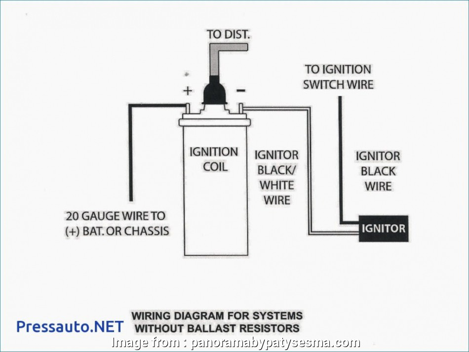
The terms used to define the model and type of the ignition coil is the primary thing. An understanding of the basic wiring diagram for ignition will provide you with a range of connections and terminals. You need to determine the kind of coil you own by examining the voltage at the primary terminal, S1. S1 must be checked for resistance to determine if the coil is type A, B or C.
The chassis’ negative should be connected to connect the coil’s low-tension side. This is exactly what you can see in the wiring diagram. The high tension part supplies positive directly the spark plugs. The aluminum body of the coil needs to be connected to the chassis to prevent it from being smothered but isn’t required. A wiring diagram can also show the connection between the positive and negative coils. In some cases it is recommended to conduct a scan at the local auto parts store will be able to diagnose malfunctioning ignition coils.
The black-and-white-striped wire from the harness goes to the negative terminal. The positive terminal receives the white wire and a trace of black. The black wire is connected to the contact breaker. It is possible to check the connections with a paperclip to remove the wires from the housing. You should also check to see that the terminals are not bent.
Accessory terminals
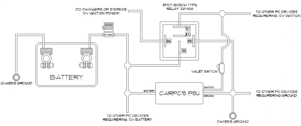
Diagrams of the ignition wiring show the wires used to provide power to various components of the vehicle. There are typically four different colors-coded terminus of each part. The accessories are red, the battery is yellow, the starter solenoid is green. The “IGN terminal” is used to power the wipers along with other operational functions. The diagram illustrates the connection between the ACC- and ST terminals.
The terminal called BAT is the place where the battery is. The battery is vital for the electrical system to begin. A dead battery can cause the switch to not come on. If you don’t know the exact location where the battery in your car is located, you can look at your wiring diagram to figure out how to locate it. The accessory terminals of your car are connected to the ignition switch and the battery. The BAT Terminal is connected to the Battery.
Some ignition switches come with an accessory position. This allows users to access their outputs from a different location without the ignition. Customers sometimes want the output of the auxiliary to be operated independently of the ignition. The auxiliary output is connected to connect the connector with the same colors as your ignition, and then connecting it to the ACC terminal of the switch. While this is an excellent option, there’s an important difference. Many ignition switches can be set to have an ACC location when the car has been moved into the ACC position. They also will be in START mode once the vehicle is entered the IGN position.
Gallery of 12 Volt Ignition Wiring Diagram
Gallery of 12 Volt Ignition Wiring Diagram


