123 Ignition Wiring Diagram – The first step is to look at the various types of terminals on the ignition switch. These terminals are used for the Ignition button, Coil and Accessory. After we’ve identified which terminals are used and which ones are not, we can determine the various components of the 123 Ignition Wiring Diagram. Then, we will discuss the functions and the Coil. Then, we’ll talk about the roles of the ignition switch and Coil.
The terminals of the ignition switch
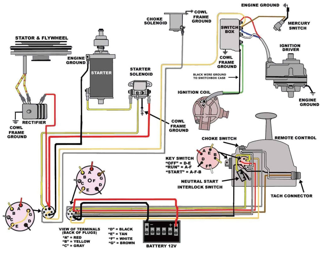
The ignition switch has three switches. They feed the battery’s voltage to different locations. The ON/OFF position of the ignition switch is controlled by the second switch, which supplies power to the choke whenever it is pushed. Different manufacturers have different colors-coding systems to match the conductors. OMC employs this system. An adapter is included on the ignition switch to allow for the addition of an tonometer.
Although some ignition switch terminals may not be original, the numbering of each one might not match the diagram. Before plugging into the ignition switch ensure that you check the continuity. A simple multimeter will help you do this. Once you’re satisfied about the integrity of the wires, then you’ll be able to connect the new connector. The wiring loom of a factory-supplied ignition system switch is distinct.
It is essential to know the ways in which the ACC outputs and auxiliary outputs function to connect them. The ACC/IGN connections function as the default connection on the ignition switch. The START/IGN terminals are connected to the stereo or radio. The ignition switch is responsible for turning the car’s engine on and off. Older cars have the ignition switch’s terminals that are labeled “ACC” or “ST” (for individual magnetowires).
Terminals for coil
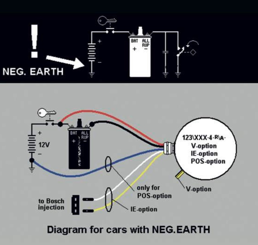
The first step in determining the kind of ignition coil is to understand the terms used. A simple diagram of the wiring will reveal a variety of terminals and connections which include two primary terminals and two secondaries. The operating voltage of each coil differs. This is why it is important to first test the voltage at the S1 (primary terminal). S1 should be tested for resistance in order to determine if the coil belongs to type A, B or C.
The coil’s low-tension side should be connected at the chassis’s plus. This is also the ground on the wiring diagram for ignition. The high-tension part provides positive direct to the sparkplugs. To reduce the noise the coil’s metal body is required to be connected to the chassis. It is not required to use electricity. The wiring diagram will also show the connection between the positive and negative coil terminals. Sometimes, a visit to an auto parts store could diagnose a malfunctioning ignition wire.
The black-and-white-striped wire from the harness goes to the negative terminal. The positive terminal is connected to the white wire and the black trace. The black wire connects to the contact breaker. If you’re not sure about the connection between the twowires, use the clip of a paperclip to remove them from the housing of the plug. Make sure that the connectors don’t bend.
Accessory terminals
Diagrams of the ignition wiring show the wiring used to provide power to various components of the car. There are typically four colors of terminals connected to each part. Accessories are red and the battery yellow the starter solenoid is green. The “IGN terminal lets you start the car, manage the wipers or other operation features. The below diagram shows how to connect both the ACC terminal and ST terminals to various components.
The terminal known as BAT is the location where the battery is. The battery is vital to allow the electrical system to begin. In addition, the switch will not start. You may refer to the wiring diagram if you’re uncertain about where the car’s batteries are. The ignition switch is connected to the battery of your car. The BAT terminal is connected to the battery.
Some ignition switches include an accessory setting where users can alter their outputs as well as control them without needing to use the ignition. Some customers prefer to use an auxiliary output independent of the ignition. For the auxiliary output to be used, plug in the connector with the same shade as the ignition. Connect it to the ACC end of the switch. Although this is a fantastic feature, there’s one thing you need to know. Most ignition switches will have an ACC position when the vehicle is in the ACC however, they will be at the START position if the car is in IGN.
Gallery of 123 Ignition Wiring Diagram
Gallery of 123 Ignition Wiring Diagram


